Hyundai Tucson: Starting System- Description
The starting system includes the battery, starter, solenoid switch, ignition switch, ignition lock switch, connection wires and the battery cable.
When the ignition key is turned to the start position, current flows and energizes the starter motor's solenoid coil.
The solenoid plunger and clutch shift lever are activated, and the clutch pinion engages the ring gear.
The contacts close and the starter motor cranks.
In order to prevent damage caused by excessive rotation of the starter armature when the engine starts, the clutch pinion gear overruns.
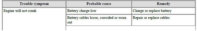
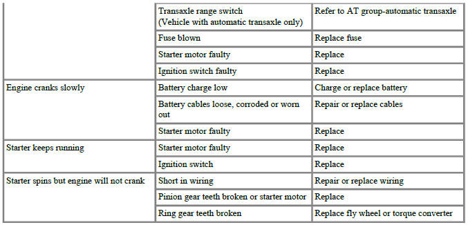
Troubleshooting
WARNING
The battery must be in good condition and fully charged for this troubleshooting
Starting system- Description
The starting system includes the battery, starter, solenoid switch, ignition switch, ignition lock switch, connection wires and the battery cable.
When the ignition key is turned to the start position, current flows and energizes the starter motor's solenoid coil.
The solenoid plunger and clutch shift lever are activated, and the clutch pinion engages the ring gear.
The contacts close and the starter motor cranks.
In order to prevent damage caused by excessive rotation of the starter armature when the engine starts, the clutch pinion gear overruns.
- Solenoid
- Brush assembly
- Armature
- Overrun clutch
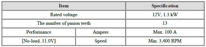
Specification
Starter
Circuit Diagram
READ NEXT:
 Engine Mechanical System - Removal
Removal
Turn the ignition switch OFF and disconnect the battery (-) terminal.
Remove the air cleaner assembly.
(Refer to Engine Mechanical System - "Air Cleaner")
Remove the engine room under cover.
(Refer to Engine Mechanic
Engine Mechanical System - Installation
Installation
Install in the reverse order of removal.
Disassembly
Remove the M-terminal nut (A) on the magnetic switch assembly (B).
After loosening the screws (A), remove the magnetic switch assembly.
Remove the throug
Free Running Inspection
Place the starter motor in a vise equipped with soft jaws and connect a
fully-charged 12-volt battery to
starter motor as follows.
Connect a test ammeter (150-ampere scale) and carbon pile rheostats
shown is the illustration.
Connect a
SEE MORE:
Front wheel speed sensor/ Front wheel speed sensor connector
Components
Front wheel speed sensor
Front wheel speed sensor connector
Removal
Loosen the wheel nuts slightly.
Raise the vehicle, and make sure it is securely supported.
Remove the front wheel and tire (A) from the front hub.
Integrated memory system
The IMS, or Integrated Memory System,
for the driver's seat is equipped on some
models. This feature allows the driver
to store and recall the following position
settings with a simple button operation:
Driver's seat position
WARNING
Information
- Home
- Hyundai Tucson - Fourth generation (NX4) - (2020-2023) - Owner's Manual
- Hyundai Tucson - Fourth generation (NX4) - (2020-2023) - Workshop Manual
