Hyundai Tucson: Engine Mechanical System - Installation
Hyundai Tucson - Fourth generation (NX4) - (2020-2023) - Workshop Manual / Engine Electrical System / Starting System / Engine Mechanical System - Installation
Installation
- Install in the reverse order of removal.
Disassembly
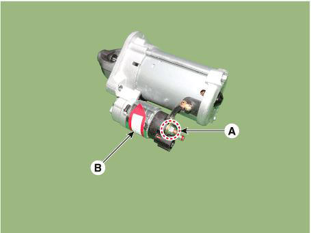
- Remove the M-terminal nut (A) on the magnetic switch assembly (B).
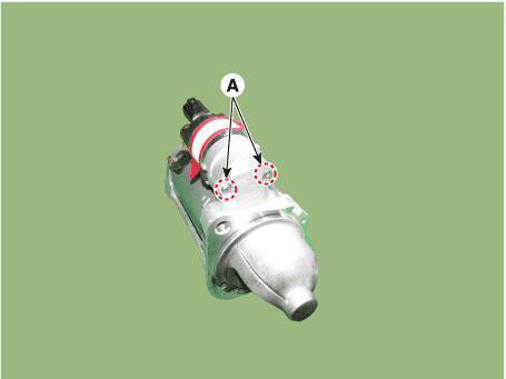
- After loosening the screws (A), remove the magnetic switch assembly.
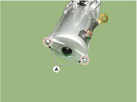
- Remove the through bolts (A).
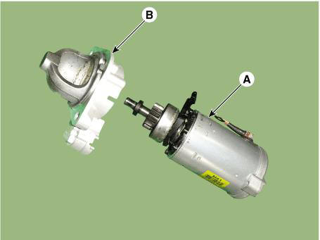
- Remove the front bracket (B) from the planet gear shaft and yoke assembly (A).
- Remove the lever (A).
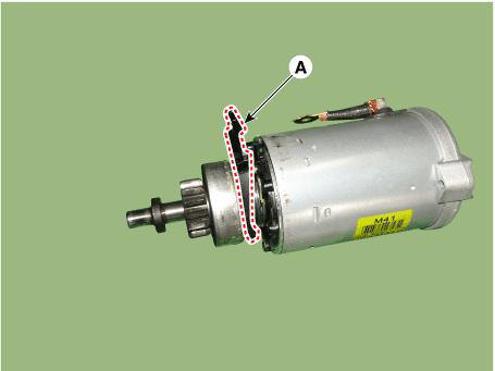
- Remove the brush holder assembly cover cap (A).

- Remove the C-ring (A).
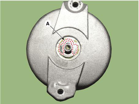
- Remove the brush holder assembly cover (A).
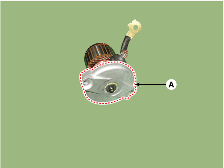
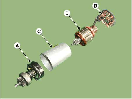
- Detach the planet gear shaft assembly (A), brush holder assembly (B), armature assembly (D) and yoke assembly (C).
- Remove the gasket seat (A).
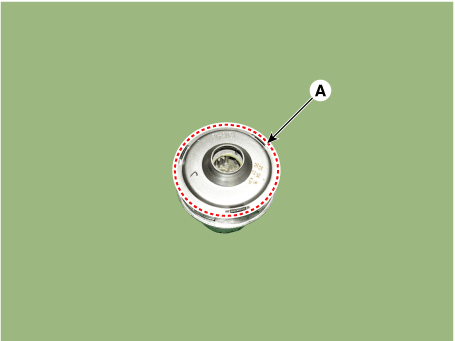
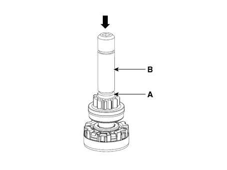
- Pass the stopper (A) using a socket (B).
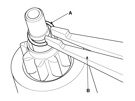
- Remove the stop ring (A) using the stop ring pliers (B).
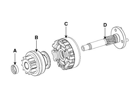
- Remove the stopper (A), overrunning clutch (B), internal gear (C) and planet shaft (D).
WARNING
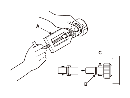
Using a suitable pulling tool (A), pull the
overrunning clutch stop ring (B) over the stopper (C)
Reassembly
- Reassemble in the reverse order of disassembly.
Inspection
Starter Solenoid Inspection
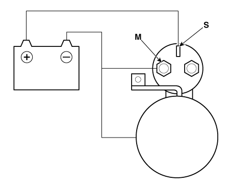
- Disconnect the lead wire from the M-terminal of solenoid switch.
- Connect the battery as shown. If the starter pinion pops out, it is working properly.
WARNING
To avoid damaging the starter, do not leave the battery connected
for more than 10 seconds.
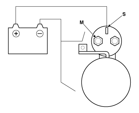
- Disconnect the battery from the M terminal.
If the pinion does not retract, the hold-in coil is working properly.
WARNING
To avoid damaging the starter, do not leave the battery connected
for more than 10 seconds.

- Disconnect the battery also from the body. If the pinion retracts immediately, it is working property
WARNING
To avoid damaging the starter, do not leave the battery connected
for more than 10 seconds.
READ NEXT:
 Free Running Inspection
Place the starter motor in a vise equipped with soft jaws and connect a
fully-charged 12-volt battery to
starter motor as follows.
Connect a test ammeter (150-ampere scale) and carbon pile rheostats
shown is the illustration.
Connect a
Starter Brush Holder Test
Check that there is no continuity between the (+) brush holder (A) and
(-) plate (B). If there is continuity,
replace the brush holder assembly.
Inspect Overrunning Clutch
Slide the overrunning clutch along the shaft.
Replace i
SEE MORE:
Electronic Stability Control System- Components
ESC Control unit (HECU)
Front wheel speed sensor
Rear wheel speed sensor
ABS warning lamp
Parking brake / EBD
Failure
Diagnosis
In principle, ESC and TCS controls are prohibited in case of ABS
failure.
When ESC or TCS fail
Snow or icy conditions
The severe weather conditions of winter
quickly wear out tires and cause other
problems. To minimize winter driving
problems, you should take the following
suggestions:
You need to keep sufficient distance
between your vehicle and the vehicle i
Information
- Home
- Hyundai Tucson - Fourth generation (NX4) - (2020-2023) - Owner's Manual
- Hyundai Tucson - Fourth generation (NX4) - (2020-2023) - Workshop Manual
