Hyundai Tucson: Free Running Inspection
Hyundai Tucson - Fourth generation (NX4) - (2020-2023) - Workshop Manual / Engine Electrical System / Starting System / Free Running Inspection
- Place the starter motor in a vise equipped with soft jaws and connect a fully-charged 12-volt battery to starter motor as follows.
- Connect a test ammeter (150-ampere scale) and carbon pile rheostats shown is the illustration.
- Connect a voltmeter (15-volt scale) across starter motor.
- Rotate carbon pile to the off position.
- Connect the battery cable from battery's negative post to the starter motor body.
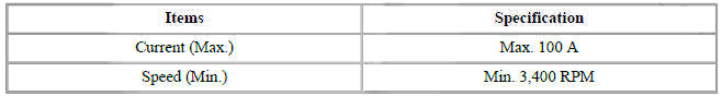
- Adjust until battery voltage shown on the voltmeter reads 11.5 and 11 volts.
- Confirm that the maximum amperage is within the specifications and that the starter motor turns smoothly and freely.
Armature Inspection and Test
- Remove the starter.
- Disassemble the starter as shown at the beginning of this procedure.
- Inspect the armature for wear or damage from contact with the permanent magnet. If there is wear or damage, replace the armature.
- Check the commutator (A) surface. If the surface is dirty or burnt, resurface with emery cloth or a lathe within the following specifications, or recondition with #500 or #600 sandpaper (B).
- Measure the commutator (A) runout.
- If the commutator runout is within the service limit, check the commutator for carbon dust or brass chips between the segments.
- If the commutator run out is not within the service limit, replace the armature.
Commutator runout
Standard (New) : 0.05 mm (0.0019 in.) max
Service limit : 0.08 mm (0.0031 in.)
- Check the mica depth (A). If the mica is too high (B), undercut the mica with a hacksaw blade to the proper depth. Cut away all the mica (C) between the commutator segments. The undercut should not be too shallow, too narrow, or v-shaped (D).
Commutator mica depth
Standard (New) : 0.7 mm (0.0276 in.)
Limit : 0.2 mm (0.0079 in.)
- Check for continuity between the segments of the commutator. If an open circuit exists between any segments, replace the armature.
- Check with an ohmmeter that no continuity exists between the commutator (A) and armature coil core (B), and between the commutator and armature shaft (C). If continuity exists, replace the armature.
Inspect Starter Brush
Any worn out or oil-soaked brushes should be replaced.
READ NEXT:
 Starter Brush Holder Test
Check that there is no continuity between the (+) brush holder (A) and
(-) plate (B). If there is continuity,
replace the brush holder assembly.
Inspect Overrunning Clutch
Slide the overrunning clutch along the shaft.
Replace i
Components and Components Location
Components Location
Crankcase Pressure Regulating Valve (PRV)
Purge Control Solenoid Valve (PCSV)
Canister
Fuel Tank Air Filter
GPF (Gasoline Particulate Filter)
Catalytic Converter (WCC)
1. Crankcase Pressure Regulating Valve (P
SEE MORE:
Reclining Motor Limit Switch
Disconnect the limit switch and operate the limit switch and then check
for continuity between the
terminals.
Make sure that the seat operation is normal in the reverse after the
maximum operation.
If there is an abnormality, replace t
Engine Coolant Temperature Sensor (ECTS)
Description
The Engine Coolant Temperature Sensor (ECTS) is located in the cylinder block
and cylinder head,
and measures the temperature of the engine coolant. The thermistor of the
cooling water temperature
and resistance has a negative temp
Information
- Home
- Hyundai Tucson - Fourth generation (NX4) - (2020-2023) - Owner's Manual
- Hyundai Tucson - Fourth generation (NX4) - (2020-2023) - Workshop Manual
