Hyundai Tucson: Starter Brush Holder Test
Hyundai Tucson - Fourth generation (NX4) - (2020-2023) - Workshop Manual / Engine Electrical System / Starting System / Starter Brush Holder Test
- Check that there is no continuity between the (+) brush holder (A) and (-) plate (B). If there is continuity, replace the brush holder assembly.
Inspect Overrunning Clutch
- Slide the overrunning clutch along the shaft.
Replace if it does not slide smoothly.
- Rotate the overrunning clutch both ways.
Does it lock in one direction and rotate smoothly in reverse? If it does not lock in either direction or locks in both directions, replace it.
- If the starter drive gear is worn or damaged, replace the overrunning clutch assembly. (The gear is not available separately.) Check the condition of the flywheel or torque converter ring gear if the starter drive gear teeth are damaged.
Cleaning
- Do not immerse parts in cleaning solvent.
Immersing the yoke assembly and/or armature will damage the insulation wipe these parts with a cloth only.
- Do not immerse the drive unit in cleaning solvent.
The overrun clutch is pre-lubricated at the factory and solvent will wash lubrication from the clutch.
- The drive unit may be cleaned with a brush moistened with cleaning solvent and wiped dry with a cloth.
Inspection
- Turn ignition switch OFF and disconnect the battery negative (-) terminal.
- Remove the fuse box cover.
- Remove the starter relay (A).
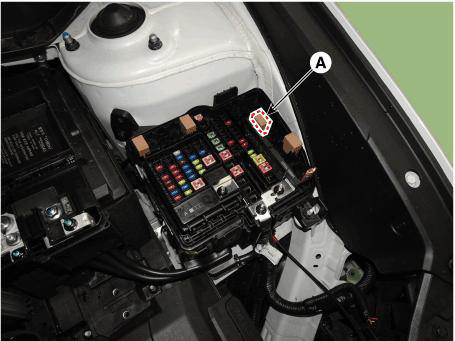
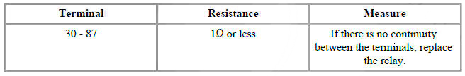
- Check for continuity between the terminals (30 and 87) using an ohmmeter.
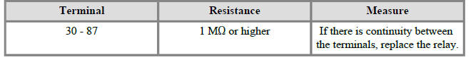
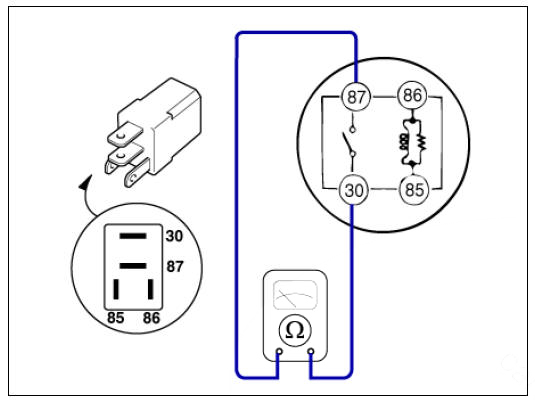
- Apply 12V to the terminal 85 and ground to the terminal 86 and then check for continuity between the terminals (30 and 87).
- Install the starter relay.
- Install the fuse box cover.
READ NEXT:
 Components and Components Location
Components Location
Crankcase Pressure Regulating Valve (PRV)
Purge Control Solenoid Valve (PCSV)
Canister
Fuel Tank Air Filter
GPF (Gasoline Particulate Filter)
Catalytic Converter (WCC)
1. Crankcase Pressure Regulating Valve (P
Crankcase Emission Control System
Description
Crankcase pressure regulating valve (PRV)
Breather hose
Air flow
Intake manifold
Cylinder block
Blow-by gas flow
Blow-by gas inflow to the cylinder head cover throungh the cylinder
block & head & chain c
SEE MORE:
Symptom Troubleshooting Guide Chart
Specifications
Fuel Delivery System
Sensors
Manifold Absolute Pressure Sensor (MAPS)
Type : Piezo-Resistive Pressure
Sensor type
Specification
Intake Air Temperature Sensor (IATS)
Type : Termistor type
Specific
External Control Valve Compressor Inspection (GDS)
Compressor type: Fixed type compressor, External control valve, Internal
control valve.
In cases of fixed type and internal control valve, it is possible to inspect
compressor's operation with clutch noise.
When it comes to External con
Information
- Home
- Hyundai Tucson - Fourth generation (NX4) - (2020-2023) - Owner's Manual
- Hyundai Tucson - Fourth generation (NX4) - (2020-2023) - Workshop Manual
