Hyundai Tucson: Front Radar Sensor Alignment
Hyundai Tucson - Fourth generation (NX4) - (2020-2023) - Workshop Manual / Advanced Driver Assistance System (ADAS) / Front Radar System / Front Radar Sensor Alignment
WARNING
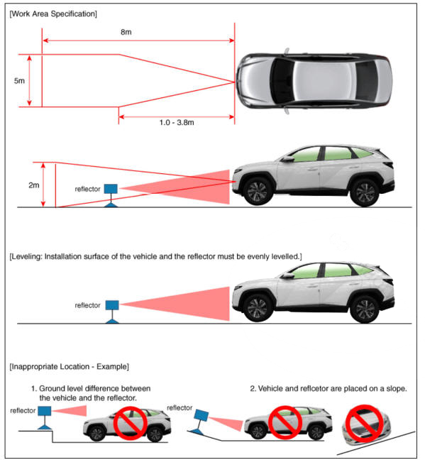
- Adjustment may not be accurate if the vehicle and reflector are placed on different ground levels or on a slope.
- Perform in an area with minimum clearance of 8 m to the front. 4 m wide, and 1.2 m above the ground.
- Remove heavy objects from inside of the vehicle (seating area and trunk).
- Ensure that all tires are filled with specified air pressure.
- Remove objects (metal plates, resins, etc.) that may cause electric signal interference from the area where sensor alignment is performed.
- Be sure that the vehicle is not moved and free from vibration when performing sensor alignment (getting in/out or opening/ closing doors).
- Check that radiator grille and sensor cover are not dirty.
- Check for correct wheel alignment.
- Do not turn OFF the power when performing sensor alignment.
- Power supplied to the radar sensor must be between 9V - 16V.
- Temperature in the area where sensor alignment is performed must be between -30 - 60ºC.
- Park the vehicle on a level ground.
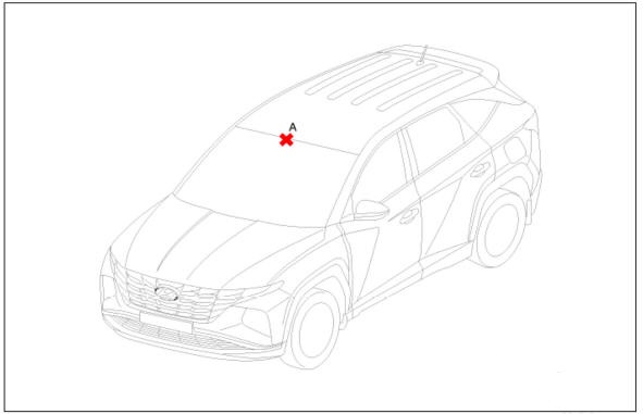
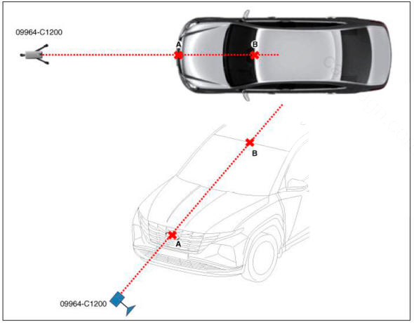
- Mark the center point 011 top of wind glass (A).
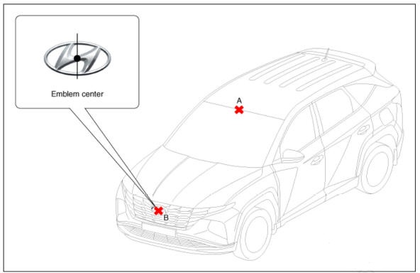
- Mark the center point of emblem (A).
- Mount the FCA Calibration Laser SST No. : 09964-C1200 onto the tripod SST No. : 09964-C1300,
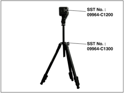
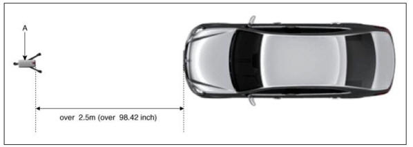
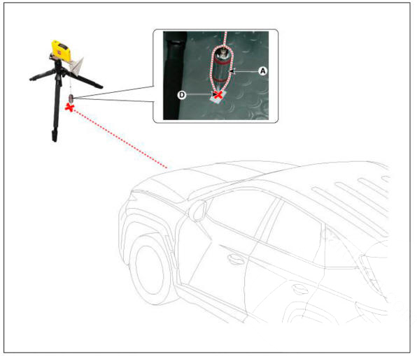
- Install the vertical/horizontal laser SST No. : 09964-C1200 (A) at least 2.5 m to the front of the vehicle.
- Match the vertical line of laser to (A) and (B) using the vertical/horizontal laser (C) SST No. : 09964-C1200.
- Mark (C) at 2.3 - 2.5m (90.55 - 98.42 inch) from (A) in front of the vehicle.
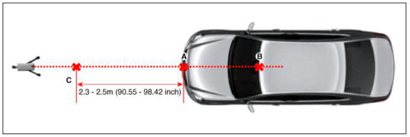
WARNING
If possible, perform calibration at the 2.5m position.
- Remove the FCA Calibration Laser SST No. : 09964-C1200 (B) from the tripod SST No. : 09964-C1300 (A).

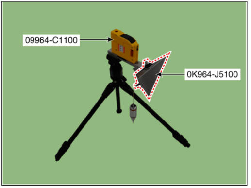
- Mount the reflector SST No. : 09964-C1100 (B) onto the tripod SST No. : 09964-C1300 (A).
- Mount the reflector adapter (0K964-J5100) to the reflector (09964-C1100).
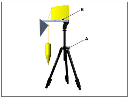
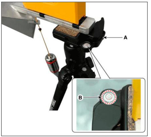
- Align the vertical weight (A) of the FCA Calibration Reflector SST No. : 09964-C1100 with the point (D).
- Using the bubble level (B) of the tripod SST No. : 09964-C1300 (A), set the reflector horizontally.
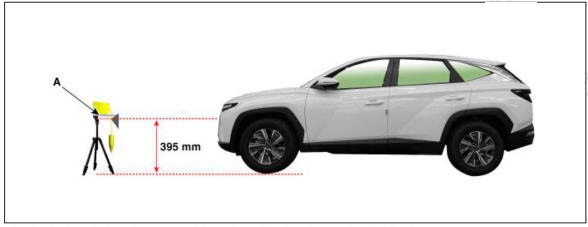
- Set the height of the FCA calibration reflector SST No. : 09964-C1100 (A) to 395 mm (15.55 inch).
- Visually check again the radar sensor and the surface of the front bumper for the following.
WARNING
- Make sure that there is no debris, or reflecting object on the surface of the radar.
- Make sure that there is no debris, or reflecting object on the radiator grille.
- Connect the GDS to the DLC of the vehicle and start sensor alignment.
WARNING
If the engine is running, the vibration may cause inaccurate sensor alignment, so perform sensor alignment in IG ON mode.
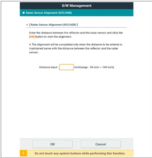
- After correctly selecting the vehicle model, select "FCA Alignment" from the auxiliary functions in GDS Menu.
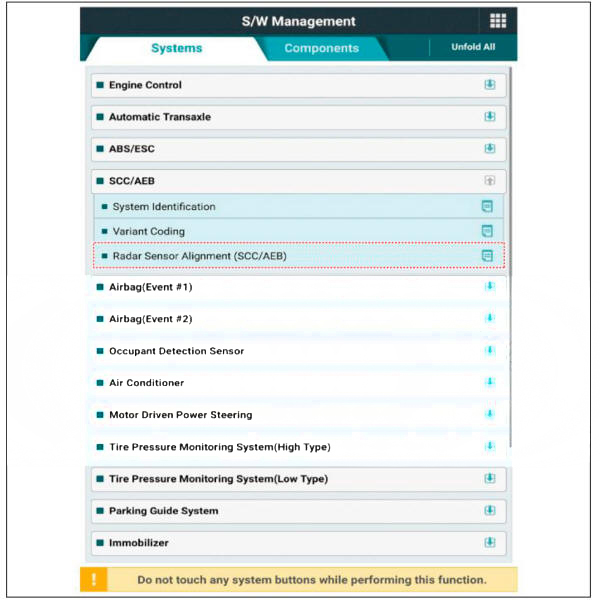
- Perform sensor alignment as indicated on the GDS monitor.
- In case of sensor alignment failure, check the alignment conditions. Turn the ignition key OFF. then reperform the sensor alignment procedure.
READ NEXT:
 Remote control switch
Components
Remote control switch (LH : Audio)
Remote control switch (RH : Trip + C'nuse)
Circuit Diagram
Trip+SCC+MSLA+LFA
Inspection
Check for resistance between terminals in right switch position.
Trip/Cruise
System Interface
Description
Rear Corner Radar is a system that measures the relative speed and distance
from the following vehicles by using two
electromagnetic wave radar sensors attached to the rear bumper, and detects any
vehicle within the blind spot zone
SEE MORE:
Operation for each function of button starting
Electric power ON / Ignition ON
The electric power state changes within the range of OFF ->ACC->IGN->OFF
by pressing the button without stepping on
the brake (Or with stepping on the brake) inside the car with FOB key (However.
DCT (Dual Clutch Transmission) System (SBW)- Inspection
Inspection
WARNING
In principle, the transmission oil is maintenance-free, and no
exchange is required.
But it must be inspected and replenished every 4 years or 40,000 miles.
Uplift the vehicle with lift.
Remove the engine room under co
Information
- Home
- Hyundai Tucson - Fourth generation (NX4) - (2020-2023) - Owner's Manual
- Hyundai Tucson - Fourth generation (NX4) - (2020-2023) - Workshop Manual
