Hyundai Tucson: Remote control switch
Components
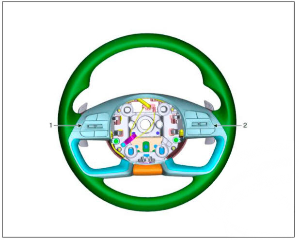
- Remote control switch (LH : Audio)
- Remote control switch (RH : Trip + C'nuse)
Circuit Diagram
Trip+SCC+MSLA+LFA
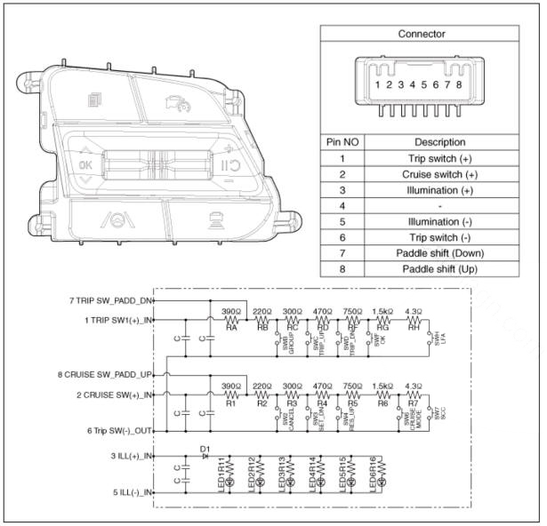
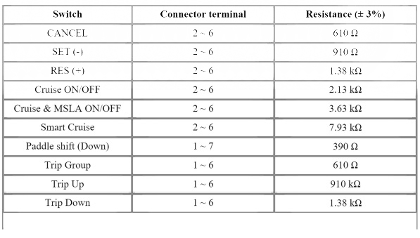
Inspection
- Check for resistance between terminals in right switch position.
Trip/Cruise
Removal
- Disconnect the negative (-) battery terminal.
- Remove the steering wheel.
(Refer to Steering System - "Steering Wheel")
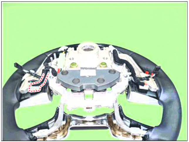
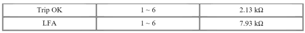
- Remove the paddle shift lever (A).
- Disconnect paddle shift lever connector (A).
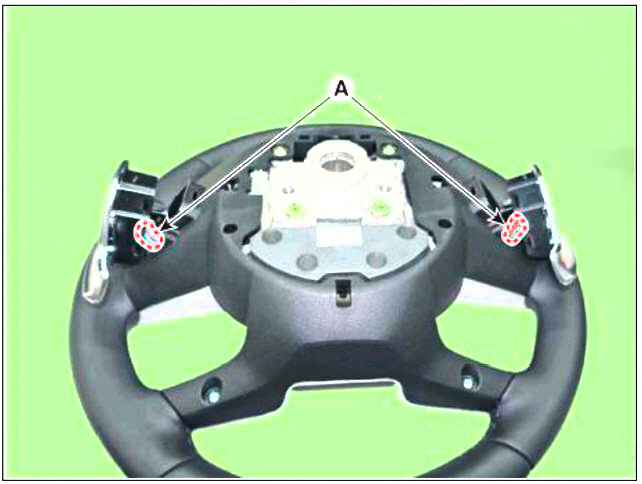
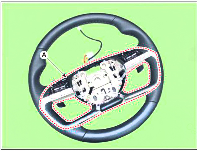
- Remove the steering wheel cover (A) after loosening mounting screws.
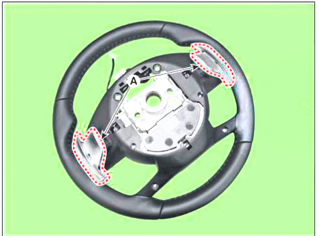
- Discoonect remote control switch connector (A) after loosening mounting screws.
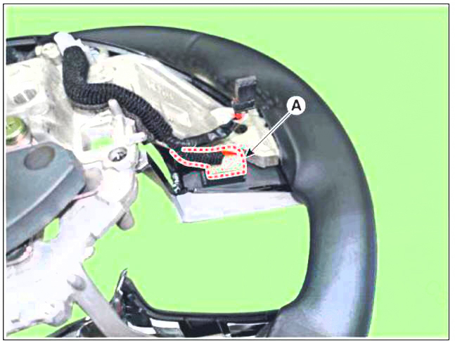
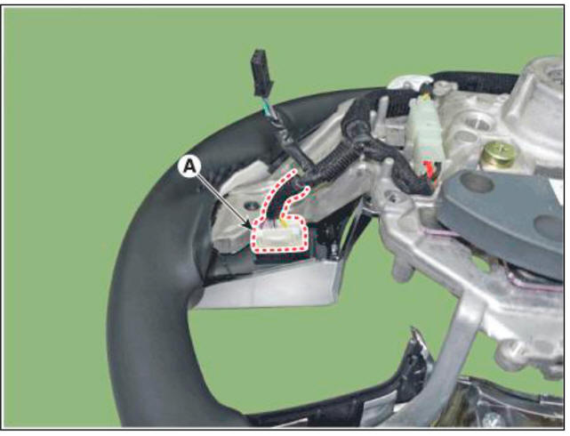
- Remove the remote control switch (A) after loosening mounting screws.
Installation
- Install the remote control switch on the steering wheel.
- Install the steering wheel lower cover.
- Install the paddle shift lever.
- Install the steering wheel.
- Connect the negative (-) battery terminal.
WARNING
- Make sure that the cables and connectors are plugged in properly.
- Check the AVN system for normal operation.
READ NEXT:
 System Interface
Description
Rear Corner Radar is a system that measures the relative speed and distance
from the following vehicles by using two
electromagnetic wave radar sensors attached to the rear bumper, and detects any
vehicle within the blind spot zone
Warning Condition
Blind-Spot Collision Warning (BCW)
BCW activating conditions
(1) User Setting Menu (USM): Select 'Driver Assistance' -> 'Blind-Spot
Safety' -- 'Blind-Spot Collision Warning'
(2) Vehicle speed: 20 kmh or faster
(3
SEE MORE:
Vehicle load limit
Two labels on your driver's door sill show
how much weight your vehicle was
designed to carry: the Tire and Loading
Information Label and the Certification
Label.
Before loading your vehicle, familiarize
yourself with the following terms for
When Ignition Key Is Turned ON (engine OFF), The ABS Warning Lamp Does Not
Light Up.
Detecting condition
When current flows in the HECU the ABS warning lamp turns from ON
to OFF as the initial check. Therefore if the lamp does not light up. the
cause may be an open in the lamp power supply circuit, a blown bulb, an
open in the bo
Information
- Home
- Hyundai Tucson - Fourth generation (NX4) - (2020-2023) - Owner's Manual
- Hyundai Tucson - Fourth generation (NX4) - (2020-2023) - Workshop Manual
