Hyundai Tucson: Roll rod bracket
- Remove the engine room under cover.
(Refer to Engine and Transaxle Assembly - "Engine Room Under Cover")
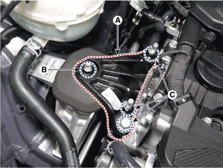
- Remove the roll rod bracket (A).
Tightening torque :
Bolt (B): 107.9 - 127.5 N.m (11.0 - 13.0 kgf.m, 79.6 - 94.0 lb-ft)
Bolts (C): 49.0 - 63.7 N.m (5.0 - 6.5 kgf.m, 36.2 - 47.0 lb-ft)
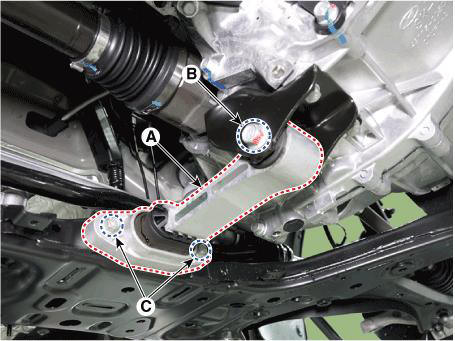
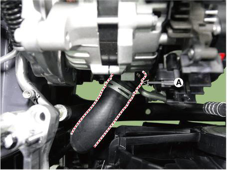
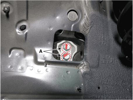
- Remove the roll rod support bracket (A).
Tightening torque : 49.0 - 68.6 N.m (5.0 - 7.0 kgf.m, 36.2 - 50.6 lb-ft)

- Installation is in the reverse order of removal.
Removal
WARNING
- Use fender covers to avoid damaging painted surfaces.
- To avoid damage, unplug the wiring connectors carefully while holding the connector portion.
WARNING
Mark all wiring connector and hoses to avoid misconnection.
- Disconnect the negative battery terminal.
- Remove the engine cover.
(Refer to Engine and Transaxle Assembly - "Engine Cover")
- Remove the engine room under cover.
(Refer to Engine and Transaxle Assembly - "Engine Room Under Cover")
- Drain the coolant.
(Refer to Cooling System - "Coolant")
- Recover the A/C refrigerant and then remove the high & low pressure pipes of A/C compressor.
(Refer to Heating, Ventilation Air conditioning - "Refreigerant Line")
- Remove the air duct and air cleaner assembly.
(Refer to Intake and Exhaust System - "Air Cleaner")
- Remove the battery and battery tray.
(Refer to Engine Electrical System - "Battery")
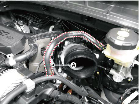
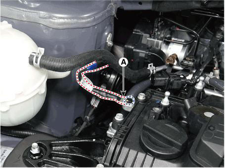
- Disconnect the brake booster vacuum hose (A).
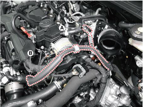
- Disconnect the fuel hose (A) and PCSV hose (B).
- Disconnect the wiring connectors and harness clamps and remove the connector brackets around the engine and transaxle assembly.
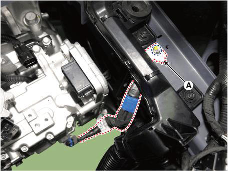
- Disconnect the engine ground cable (A).
Tightening torque : 6.8 - 9.8 N.m (0.7 - 1.0 kgf.m, 5.1 - 7.2 lb-ft)
- Disconnect the transaxle ground cable (A).
Tightening torque : 10.8 - 13.7 N.m (1.1 - 1.4 kgf.m, 8.0 - 10.1 lb-ft)
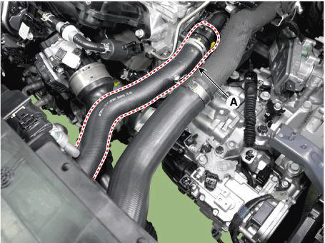
- Disconnect the intercooler inlet hose (A).
Tightening torque : Clamp bolt: 4.9 - 6.9 N.m (0.5 - 0.7 kgf.m, 3.6 - 5.1 lb-ft)
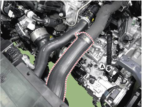
WARNING
Insert the hose until it reaches the end of stopper.
- Remove the intercooler outlet hose (A).

WARNING
1) When disconnecting the intercooler hose, pull the quick connector
clamp (A) in the direction of the
arrow as below. 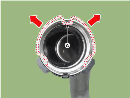
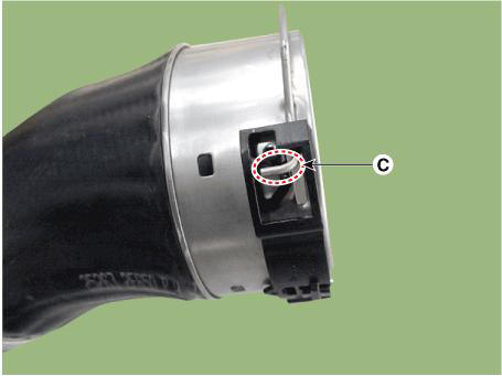
2) Move the quick connector clamp from B to C position as below and
then disconnect by pulling the
quick connector hose. 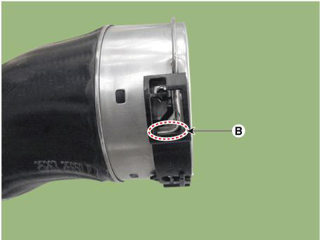
- Disconnct the radiator upper hose (A).
- Disconnct the radiator lower hose (A).
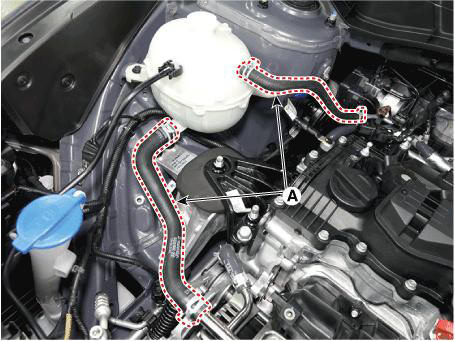
- Disconnect the coolant reservoir tank water hoses (A).
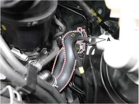
- Disconnect the heater hoses (A).
- Remove the universal joint from the shaft joint
(Refer to Steering System - "Steering Gear Box")
- Remove the front muffler.
(Refer to Intake And Exhaust System - "Muffler")
- Remove the propeller shaft. 4WD
(Refer to Driveshaft and Axle - "Propeller Shaft")
- Remove the roll rod bracket (A).
Tightening torque :
Bolt (B): 107.9 - 127.5 N.m (11.0 - 13.0 kgf.m, 79.6 - 94.0 lb-ft)
Bolts (C): 49.0 - 63.7 N.m (5.0 - 6.5 kgf.m, 36.2 - 47.0 lb-ft)

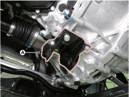
- Remove the roll rod mounting support bracket (A).
Tightening torque : 49.0 - 68.6 N.m (5.0 - 7.0 kgf.m, 36.2 - 50.6 lb-ft)
- Remove the sub frame.
(Refer to Suspension System - "Sub frame")
- Support the engine and transaxle assembly safely with a floor jack.
- Remove the engine mounting support bracket (A).
Tightening torque : Bolt and Nut (B, C) : 88.3 - 107.9 N.m (9.0 - 11.0 kgf.m, 65.1 - 79.6 lb-ft)
- Remove the LH front wheel guard.
(Refer to Body (Interior and Exterior) - "Front Wheel Guard")
- Loosen the transaxle support bracket mounting bolts (A).
Tightening torque :
107.9 - 127.5N.m (11.0 - 13.0 kgf.m, 79.6 - 94.0 lb-ft)
- Remove the engine and transaxle assembly from a vehicle by slowly lifting off the vehicle
WARNING
- Before removing the engine assembly, make sure to check that the hoses and wire connectors are completely disconnected.
- When removing the engine and transaxle assembly, be careful not to damage any surrounding parts or body components.
- Install in the reverse order of removal.
WARNING
- Refill a radiator and a reservoir tank with engine coolant.
(Refer to Cooling System - "Coolant")
- Check the engine oil level.
If necessary, refill engine with engine oil.
- Check the transaxle oil level.
If necessary, refill a transaxle with fluid.
- Charging the refrigerant gas.
- Inspect for fuel leakage.
READ NEXT:
 Air Cleaner Assembly
Removal and
Installation
Disconnect the battery negative terminal.
Disconnect the air flow sensor (AFS) connector (A).
Remove the air duct (A).
Disconnect the RCV hose (A).
Remove the air cleaner assembly
Tight
Air Cleaner Element Replacement
Open the air cleaner element cover (A) by lifting up the air cleaner
element cover handle.
Unlock the air cleaner element camshaft (A) by turning in the direction
of arrow.
Replace the air cleaner element (A) with a new o
SEE MORE:
Evaporative Emission Control System - Removal
Removal
WARNING
Be careful not to damage the parts located under the vehicle (floor
under cover, canister, fuel tank)
when raising the vehicle using the lift.
(Refer to General Information - "Lift and Support Points")
Turn
ABS Does Not Operate/ ABS Does Not Operate (Intermittently)
ABS Does Not Operate
Detecting condition
Brake operation varies depending on driving conditions and road surface
conditions, so diagnosis can be difficult. However if a normal DTC is
displayed, check the following probable cause. When the problem
Information
- Home
- Hyundai Tucson - Fourth generation (NX4) - (2020-2023) - Owner's Manual
- Hyundai Tucson - Fourth generation (NX4) - (2020-2023) - Workshop Manual
