Hyundai Tucson: Piston Rings
- Inspect the piston ring side clearance.
Using a feeler gauge, measure the clearance between new piston ring and the wall of ring groove.
Piston ring groove width dimension of piston
No.1 ring : 1.230 - 1.250 mm (0.0484 - 0.0492 in.)
No.2 ring : 1.030 - 1.050 mm (0.0406 - 0.0413 in.)
Oil ring : 2.030 - 2.045 mm (0.0799 - 2.0805 in.)
Piston ring width dimension
No.1 ring : 1.170 - 1.190 mm (0.0461 - 0.0469 in.)
No.2 ring : 0.970 - 0.990 mm (0.0382 - 0.0390 in.)
Oil ring : 1.920 - 1.960 mm (0.0756 - 0.0772 in.)
Piston and piston ring side clearance
No.1 ring : 0.040 - 0.080 mm (0.0016 - 0.0031 in.)
No.2 ring : 0.040 - 0.080 mm (0.0016 - 0.0031 in.)
Oil ring : 0.050 - 0.105 mm (0.0020 - 0.0041 in.)
If the clearance is greater than maximum, replace the piston.
- Inspect the piston ring end gap.
To measure the piston ring end gap, insert a piston ring into the cylinder bore. Position the ring at right angles to the cylinder wall by gently pressing it down with a piston. Measure the gap with a feeler gauge.
If the gap exceeds the specifications, replace the piston rings. If the gap is too large, recheck the cylinder bore inner diameter.
Piston ring end gap
Standard
No.1 ring : 0.14 - 0.19 mm (0.0055 - 0.0075 in.)
No.2 ring : 0.20 - 0.30 mm (0.0079 - 0.0118 in.)
Oil ring : 0.10 - 0.40 mm (0.0039 - 0.0157 in.)
Piston Pin

- Measure the outer diameter of piston pin
Piston pin diameter : 18.997 - 19.000 mm (0.7479 - 0.7480 in.)
- Measure the piston pin-to-piston clearance.
Piston pin-to-piston clearance : 0.004 - 0.012 mm (0.0002 - 0.0005 in.)
- Check the difference between the piston pin outer diameter and the connecting rod small end inner diameter.
Piston pin-to-connecting rod interference : 0.005 - 0.014 mm (0.0002 - 0.0006 in.)
Piston Pin - Reassembly
WARNING
- Thoroughly clean all parts to assembled.
- Before installing the parts, apply fresh engine oil to all sliding and rotating surfaces.
- Always use new gaskets, O-ring and oil seals.
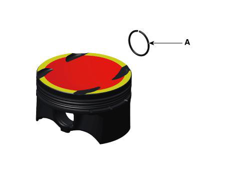
- Assemble the piston and the connecting rod.
(1) Install the snap ring (A) in one side of the piston pin hole.
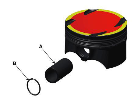
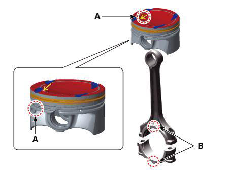
(2) Align the piston front mark (A) and the connecting rod front mark (B).

(3) Insert the piston pin (A) into the piston pin hole and the small end bore of connecting rod.
(4) Install the snap ring (B) in the other side after inserting the piston pin.
WARNING
- Before inserting the piston pin, apply sufficient engine oil on the piston's outer surface, piston hole's inner surface and connecting rod's small-end bore.
- When inserting, use caution not to damage or scratch the connecting rods' small-end hole, piston's pin hole and piston pin.
- Install the snap ring surely so that the snap ring contacts the overall groove of the piston's pin hole.
- Assemble so that the cut surface of the snap ring is located within the upper 45º range.

- Install the piston rings.
(1) Install the oil ring expander and two side rails by hand.
(2) Using a piston ring expander, install the 2 compression rings with the maker mark facing upward.
(3) Position the piston rings so that the ring ends are as shown.
WARNING
The side rail is an asymmetric barrel type and install it so that DMC mark faces upward (Cylinder head side).
At this time, paint identification mark should be positioned at the right side of ring cutting section.
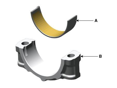
- Install the connecting rod bearings.
(1) Align the bearing (B) claw with the groove of the connecting rod or bearing cap (A).
(2) Install the bearings (B) in the connecting rod and bearing cap (A).
- Install the piston and connecting rod assembly.
WARNING
Before installing the piston, apply a coat of engine oil to the piston ring grooves and cylinder bores.
The piston front mark (A) and the connecting rod front mark (B) must face the timing chain side of the engine.
(1) Install the ring compressor, check that the rings are securely in place, then position the piston in the cylinder, and tap it in using the wooden handle of a hammer.
(2) Stop after the ring compressor pops free, and check the connecting rod-to-crank journal alignment before pushing the piston into place.
WARNING
Maintain downward force on the ring compressor to prevent the rings from expanding before entering the cylinder bore.
(3) Install the connecting rod caps (A) with bearings, and tighten the bolts.
Tightening torque : 17.7 - 21.6 N.m (1.8 - 2.2 kgf.m, 13.0 - 15.9 lb-ft) + 68 - 72º
WARNING
Always use new connecting rod cap bolts.
- Assemble the other parts in the reverse order of disassembly
READ NEXT:
 Piston Pin - Disassembly
WARNING
Use fender covers to avoid damaging painted surfaces.
To avoid damage, unplug the wiring connectors carefully while
holding the connector portion.
WARNING
Mark all wiring connector and hoses to avoid misconnection.
To releas
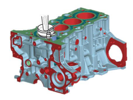
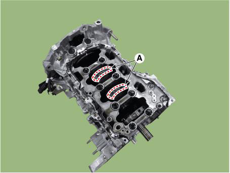
Cylinder Block Crankshaft Journal Bore Mark Location
Letters have been stamped on the side surface of the block as a mark for the
size of each of the 5 main
journal bores.
Use them, and the numbers or letters stamped on the crank (marks for main
journal size), to choose the
correct bearings.
Piston Pin - Reassembly
WARNING
Thoroughly clean all parts to assembled.
Before installing the parts, apply fresh engine oil to all
sliding and rotating surfaces.
Always use new gaskets, O-ring and oil seals.
Install the crankshaft position sensor wheel
SEE MORE:
Input shaft speed sensor- Installation
Installation
Check that the shaft is in the "N" position.
Install the position sensor (A) and then lightly tighten the bolts.
Install the position sensor "N" fixing SST(No.:09430-2Cl 10).
Tighten position
Quarter Fixed Glass
Components
Quarter fixed glass
Removal
WARNING
When removing with a flat-tip screwdriver or remover, wrap
protective tape around the tools to prevent
damage to components.
Put on gloves to prevent hand injuries.
WARNING
Tak
Information
- Home
- Hyundai Tucson - Fourth generation (NX4) - (2020-2023) - Owner's Manual
- Hyundai Tucson - Fourth generation (NX4) - (2020-2023) - Workshop Manual
