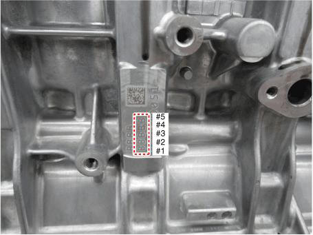
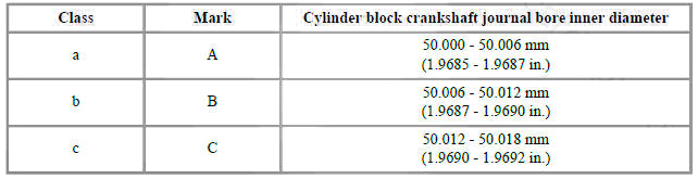
Hyundai Tucson: Cylinder Block Crankshaft Journal Bore Mark Location
Letters have been stamped on the side surface of the block as a mark for the size of each of the 5 main journal bores.
Use them, and the numbers or letters stamped on the crank (marks for main journal size), to choose the correct bearings.
Crankshaft Main Journal Mark Location
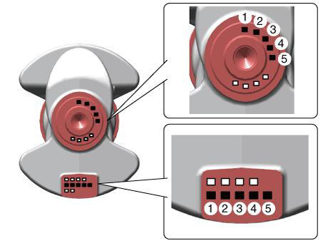
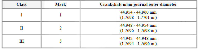
Discrimination Of Crankshaft Main Journal
Crankshaft Bearing Identification Mark Location
No. 2, No. 4 Journal Upper Bearing
No. 1, No. 3, No. 5 Journal Upper Bearing
Lower Bearing
Discrimination Of Crankshaft Bearing
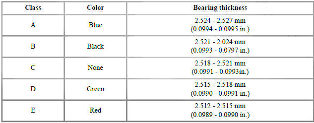
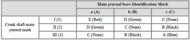
(7) Select the bearing by using selection table.
Crankshaft Main Bearing Selection Table
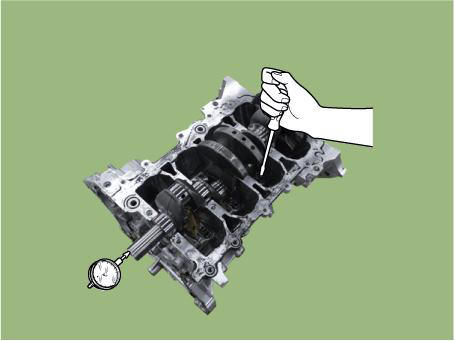
- Check the crankshaft end play.
Using a dial indicator, measure the thrust clearance while prying the crankshaft back and forth with a screwdriver.
Crankshaft end play 0.100 - 0.280 mm (0.0039 - 0.0110 in.)
If the end play is greater than maximum, replace the thrust bearings as a set.
Thickness of thrust bearing : 2.910 - 2.950 mm (0.1146 - 0.1161 in.)
- Inspect the crankshaft main journals and pin journals.
Using a micrometer, measure the diameter of each main journal and pin journal.
Main journal diameter : 44.942 - 44.960 mm (1.7694 - 1.7701 in.)
Crank pin diameter : 41.954 - 41.972 mm (1.6517 - 1.6524 in.)
READ NEXT:
 Piston Pin - Reassembly
WARNING
Thoroughly clean all parts to assembled.
Before installing the parts, apply fresh engine oil to all
sliding and rotating surfaces.
Always use new gaskets, O-ring and oil seals.
Install the crankshaft position sensor wheel
Cylinder Block/ Disassembly/ Inspection/ Reassembly
WARNING
Use fender covers to avoid damaging painted surfaces.
To avoid damage, unplug the wiring connectors carefully while
holding the connector portion.
WARNING
Mark all wiring connector and hoses to avoid misconnection.
To releas
Cylinder Head Assembly
Components
Front camshaft bearing cap
Intake camshaft bearing cap
Exhaust camshaft bearing cap
Cam carrier
Fuel pump adaptor
Engine hanger
Cylinder head
Cylinder head gasket
Intake OCV center bolt
Intake OCV center bolt
SEE MORE:
Charge and Retest method after battery charge
Battery charge
Set battery charger to 'Auto Mode' (The Mode that charging current drops as
the battery charges.) and
charge battery until charging current down close to zero or the charger alerts
you with an alarm when charge
is complete.(Mini
Trailer towing
If you are considering towing with your
vehicle, be sure to take extra precautions
while driving. Only experienced drivers
should consider towing. Plan your trip
accordingly as vehicle speed limits for
vehicles towing trailers may be different.
Information
- Home
- Hyundai Tucson - Fourth generation (NX4) - (2020-2023) - Owner's Manual
- Hyundai Tucson - Fourth generation (NX4) - (2020-2023) - Workshop Manual
