Hyundai Tucson: Piston Pin - Reassembly

WARNING
- Thoroughly clean all parts to assembled.
- Before installing the parts, apply fresh engine oil to all sliding and rotating surfaces.
- Always use new gaskets, O-ring and oil seals.
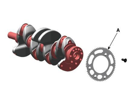
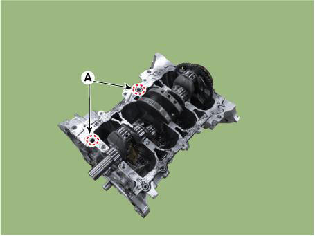
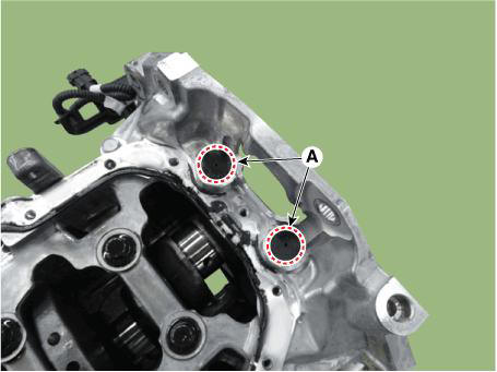
- Install the crankshaft position sensor wheel (A).
Tightening torque : 12.7 - 13.7 N.m (1.3 - 1.4 kgf.m, 9.4 - 10.1 lb-ft)
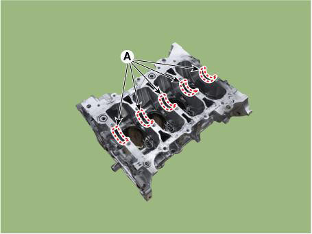
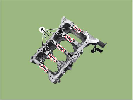
- Install the main bearing.
WARNING
- When installing the crankshaft upper bearings, the upper bearings should fit for each journal.
No. 2, No. 4 Journal Upper Bearing
No. 1, No. 3, No. 5 Journal Upper Bearing
(1) Align the bearing claw with the groove of the cylinder block, and push in the 5 upper bearings (A).
(2) Align the bearing claw with the groove of the crank lower case, and push in the 5 lower bearings (A).
(3) Apply a coat of engine oil after assembling the main bearings.
cardiagn.com
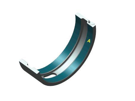
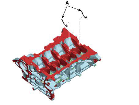
- Install the thrust bearings.
Install the 2 thrust bearings (A) on both sides of the No.4 journal of the cylinder block with the oil groove facing out.
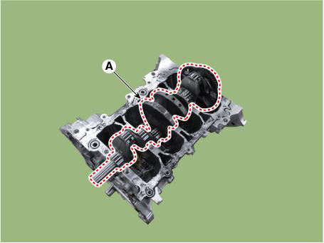
- Place the crankshaft (A) on the cylinder block.
WARNING
- When exchanging the crankshaft and short engine, apply if the pilot bearing is not assembled. DCT Only
- When press fitting the pilot bearing, press fit so that the load is applied only to the outer race of the pilot bearing.
- if load is applied to the seal and inner race, the component or
bearing inside may be damaged.
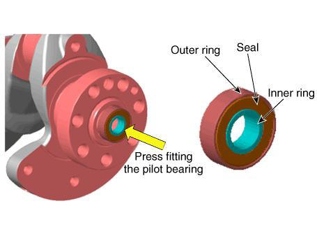
- Press-fit depth of the pilot bearing (A) : 1.5 - 2.0 mm (0.0591
- 0.0787 in) from the end of the crankshaft.
- Install the lower crankcase.
(1) Make sure to remove hardened sealant, foreign matters, oil, dust, moisture on the sealing face of the liquid gasket of the lower crankcase.
Spray the cleaner on the sealing surface and wipe it off with a clean cloth.
(2) Install the new O-ring (A) on the cylinder block.
(3) Apply liquid sealant on lower crankcase. Then, assemble the part within 5 minutes of applying sealant.
Width : 2.5 - 3.5 mm (0.0984 - 0.1378 in)
Specification : MS721-40AA or AAO / above.
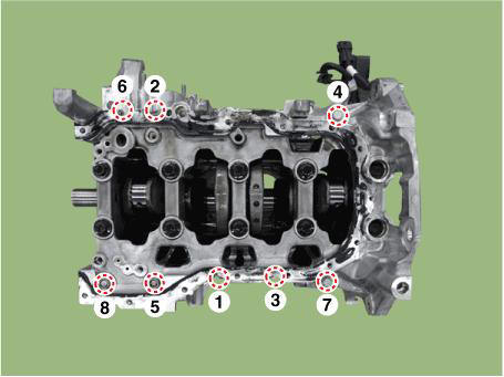
(4) Tighten the crankshaft bearing cap bolts several times according to the tightening sequence shown below.
Tightening torque : 27.5 - 31.4 N.m (2.8 - 3.2 kgf.m, 20.3 - 23.1 lb-ft) + 118 - 122º
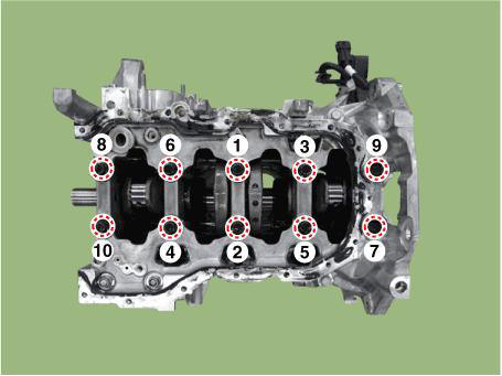
WARNING
Always use new bearing cap bolts.
(5) Tighten the lower crankcase mounting bolts several times according to the tightening sequence shown below.
Tightening torque : 18.6 - 23.5 N.m (1.9 - 2.4 kgf.m, 13.7 - 17.4 lb-ft)
(6) Install the rear caps (A).
WARNING
- When installing the rear cap, make sure that the cylinder block
installed surface and the rear cap
installed surface are aligned.
(1) Check that the crankshaft turns smoothly.
- Check the crankshaft end play.
- Install the piston and connecting rod assemblies.
(Refer to Cylinder Block - "Piston and Connecting Rod")
- Assemble the other parts in the reverse order of disassembly.
WARNING
- In case the crankshaft is replaced with a new one, select the proper connecting rod bearing according to the pin journal mark on the crankshaft.
- Connecting rod bearing selection
(Refer to Cylinder Block - "Piston and Connecting Rod")
READ NEXT:
 Cylinder Block/ Disassembly/ Inspection/ Reassembly
WARNING
Use fender covers to avoid damaging painted surfaces.
To avoid damage, unplug the wiring connectors carefully while
holding the connector portion.
WARNING
Mark all wiring connector and hoses to avoid misconnection.
To releas
Cylinder Head Assembly
Components
Front camshaft bearing cap
Intake camshaft bearing cap
Exhaust camshaft bearing cap
Cam carrier
Fuel pump adaptor
Engine hanger
Cylinder head
Cylinder head gasket
Intake OCV center bolt
Intake OCV center bolt
Cylinder Head Assembly - Removal
Disconnect the battery negative terminal.
Remove the engine cover.
(Refer to Engine and Transaxle Assembly - "Engine Cover")
Remove the air duct and air cleaner assembly.
(Refer to Intake and Exhaust System - "Air Cleane
SEE MORE:
IMS (Integrated Memory)
Description
The optimal seat position set by the driver is memorized into the power seat
unit by using IMS switch.
In case of the position change, the seat can restore its preset position by IMS
switch.
It has safety functions of restoring
Engine Coolant Temperature Sensor (ECTS)
Description
The Engine Coolant Temperature Sensor (ECTS) is located in the cylinder block
and cylinder head,
and measures the temperature of the engine coolant. The thermistor of the
cooling water temperature
and resistance has a negative temp
Information
- Home
- Hyundai Tucson - Fourth generation (NX4) - (2020-2023) - Owner's Manual
- Hyundai Tucson - Fourth generation (NX4) - (2020-2023) - Workshop Manual
