Hyundai Tucson: Cylinder Block/ Disassembly/ Inspection/ Reassembly
WARNING
- Use fender covers to avoid damaging painted surfaces.
- To avoid damage, unplug the wiring connectors carefully while holding the connector portion.
WARNING
- Mark all wiring connector and hoses to avoid misconnection.
- To release the fuel system pressure before removing the engine assembly, start the engine without fuel pump relay. Then, switch "OFF" the ignition when engine stops.
- Turn the crankshaft pulley so that the No. 1 piston is at top dead center.
- Remove the crankshaft.
(Refer to Cylinder Block - "Crankshaft")
- Remove the water jacket insert.
(Refer to Cylinder Block - "Water Jacket Insert")
- Remove the knock sensor.
(Refer to Engine Control / Fuel System - "Knock Sensor (KS)")
- Remove the crankshaft position sensor (CKPS).
(Refer to Engine Control / Fuel System - "Crankshaft Position Sensor (CKPS)")
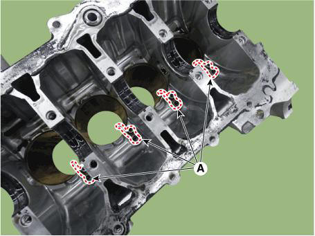
- Remove the piston cooling oil jets (A).

Inspection
- Using a gasket scraper, remove all the gasket material from the top surface of the cylinder block.
- Using a soft brush and solvent, thoroughly clean the cylinder block.
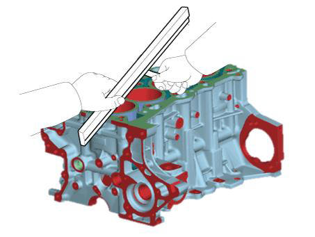
- Inspect the top surface of cylinder block for flatness.
Using a precision straight edge and feeler gauge, measure the surface contacting the cylinder head gasket for warpage.
Flatness of cylinder block gasket surface : Less than 0.05 mm (0.0020 in.) for total area
Less than 0.02 mm (0.0008 in.) for a section of 100 mm x 100 mm (3.9370 in x 3.9370 in.)
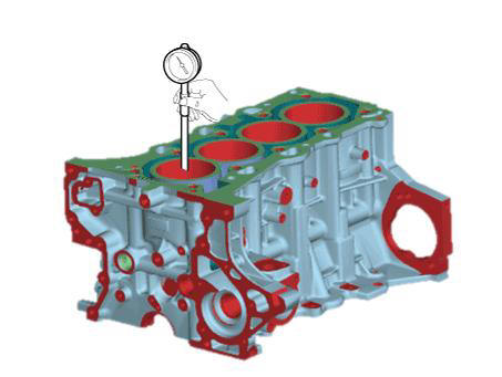
- Visually check for scratches on the inside surface of the cylinder bore and replace the cylinder block if any noticeable scratch is detected.
If deep scratchs are present, replace the cylinder block.
- Using the cylinder bore gauge, measure the cylinder bore's inner diameter to the axial and axial perpendicular directions.
Cylinder bore diameter : 75.60 - 75.63 mm (2.9764 - 2.9776 in.)
Reassembly
WARNING
- Thoroughly clean all parts to assembled.
- Before installing the parts, apply fresh engine oil to all sliding and rotating surfaces.
- Always use new gaskets, O-ring and oil seals.
- Install the piston cooling oil jets (A).
Tightening torque : 8.8 - 12.7 N.m (0.9 - 1.3 kgf.m, 6.5 - 9.4 lb-ft)
- Install the crankshaft.
(Refer to Cylinder Block - "Crankshaft")
- Check the crankshaft end play.
(Refer to Cylinder Block - "Crankshaft")
- Disconnect the lower crankcase and check crankshaft bearing oil clearance.
(Refer to Cylinder Block - "Crankshaft")
- Install the piston and connecting rod assembly.
(Refer to Cylinder Block - "Piston and Connecting Rod")
- Check the connecting rod bearing cap oil clearance.
(Refer to Cylinder Block - "Piston and Connecting Rod")
- Check the connecting rod end play.
(Refer to Cylinder Block - "Piston and Connecting Rod")
- Assemble the other parts in the reverse order of disassembly.
WARNING
- In case the cylinder block is replaced with a new one, select the proper crankshaft main bearing and the piston according to the crankshaft journal bore mark and the cylinder bore mark on the cylinder block.
- Crankshaft main bearing selection (Refer to Cylinder Block - "Crankshaft")
(Refer to Cylinder Block - "Crankshaft")
- Piston selection
(Refer to Cylinder Block - "Piston and Connecting Rod")
READ NEXT:
 Cylinder Head Assembly
Components
Front camshaft bearing cap
Intake camshaft bearing cap
Exhaust camshaft bearing cap
Cam carrier
Fuel pump adaptor
Engine hanger
Cylinder head
Cylinder head gasket
Intake OCV center bolt
Intake OCV center bolt
Cylinder Head Assembly - Removal
Disconnect the battery negative terminal.
Remove the engine cover.
(Refer to Engine and Transaxle Assembly - "Engine Cover")
Remove the air duct and air cleaner assembly.
(Refer to Intake and Exhaust System - "Air Cleane
Cylinder Head Assembly- Installation
The hardening sealant located on the upper area between timing chain
cover and cam carrier, cylinder head
cover should be removed before assembling cylinder head cover.
Install the cylinder head cover.
(1) Install the new gasket.
WARNIN
SEE MORE:
Engine oil flow diagram
Components
Variable oil pump
Variable oil pump sproket
Oil Pressure & temperature sensor
Oil filter
Filter cap O-ring
Filter cap
Safety pin
Oil cooler
Engine oil flow diagram
Replacement
WARNING
Prolonged and re
eCall Parameter Download
eCall Parameter Download is used to change the parameter value of the eCall
law in Europe.
Turn the ignition switch OFF.
Connect the diagnostic tools.
Turn the ignition switch ON without the engine running.
Select the "Car Model"
Information
- Home
- Hyundai Tucson - Fourth generation (NX4) - (2020-2023) - Owner's Manual
- Hyundai Tucson - Fourth generation (NX4) - (2020-2023) - Workshop Manual
