Hyundai Tucson: Inhibitor switch/ Manual control lever
Hyundai Tucson - Fourth generation (NX4) - (2020-2023) - Workshop Manual / DCT (Dual Clutch Transmission) System / DCT (Dual Clutch Transmission) System (SBC) / Inhibitor switch/ Manual control lever
Components
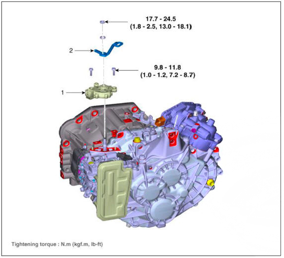
- Inhibitor switch
- Manual control lever
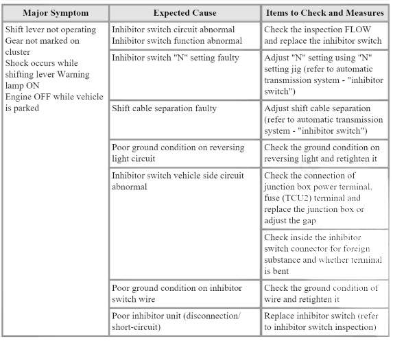
Fault Diagnosis
Fault Diagnosis for Symptom
Specifications
Signal Code Table
Inspection
WARNING
Thoroughly check connectors for looseness, poor connection, bending, corrosion, contamination, deterioration, or damage.
Inspection flow
Items to check
- Inspect DTC code.
- Inspect whether N setting matches.
- Adjust N setting (refer to automatic transmission system - "inhibitor switch")
- Inspect shift cable separation.
- Adjust shift cable separation (refer to automatic transmission system - "shift cable")
- Inspect whether connector is connected.
- Inspect connector thoroughly for looseness, poor connection, bending, corrosion, contamination, deformation, or damage.
- Turn ignition key "ON" and engine "OFF" and measure the power supplied to inhibitor switch circuit and voltage between ground.
Specification : approx. 12 V
- F i x the pin wiring when connector pin wiring is faulty (refer to ETM - "wiring repair").
- Inspect ground condition on reversing light circuit.
- Check the ground location of reversing light (refer to ETM - "harness location map").
- Reattach reversing light if ground condition is faulty.
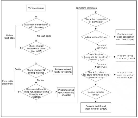
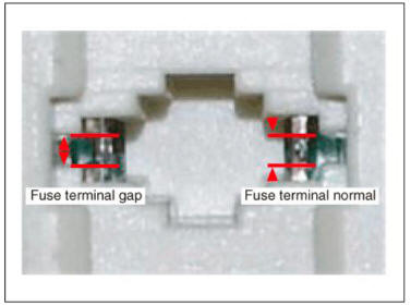
- Inspect wiring connection on junction box power terminal and fuse lamp.
- Check whether fuse holder is separated and holder is holding the fuse tight.
- Attach tester fuse to check if it is connected appropriately.
- Check whether fuse capacity is appropriate for each circuit.
- Check if fuse is damaged.
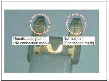
- Check pulling of fuse fixing wiring, inflow of foreign substance, and arrangement condition of terminal.
- Relocate the terminal that has been pulled and inspect using the method explained above.
- When problem is not solved, refer to the circuit diagram wiring repair instructions to fix or replace the terminal.
- Inspect inhibitor switch signal.
- Turn ignition key "ON" and engine "OFF".
- Measure the voltage between each terminal and chassis ground when shifting lever to "P. R. N, D" range.
Specified value: refer to specification "signal code" table
READ NEXT:
 Inhibitor switch/ Manual control lever- Removal
Turn ignition switch OFF and disconnect the batteiy negative (-)
terminal.
Make sure vehicle does not roll before setting shift lever to "N"
position.
Remove the air cleaner assembly and air duct.
(Refer to Engine Mechanical
Shift lever knob & boots assembly
Components
Shift lever knob & boots assembly
Shift lever assembly
Shift cable
Manual control lever
Shift cable retainer
Removal
Remove the shift lever knob & boots (A) pull both of it up.
Remove the floor consol
Shift gear
Components
Shift lever knob & boots assembly
Shift lever assembly
Shift cable
Manual control lever
Shift cable retainer
Removal
Turn ignition switch OFF and disconnect the negative (-) batteiy cable.
Remove the air cleane
SEE MORE:
In-car sensor
Components Location
In-car sensor
Replacement
Disconnect the negative (-) battery terminal.
Remove the crash pad center panel.
(Refer to Body (Interior and Exterior) - "Crash Pad Center Panel")
Using a screwdriver or re
Front Suspension System- Replacement
Replacement
WARNING
When lifting a vehicle using a lift, be careful not to damage the
lower parts of the vehicle (floor under
cover, fuel filter, fuel tank, canister).
(Refer to General Information - "Lift Point")
Loosen the fro
Information
- Home
- Hyundai Tucson - Fourth generation (NX4) - (2020-2023) - Owner's Manual
- Hyundai Tucson - Fourth generation (NX4) - (2020-2023) - Workshop Manual
