Hyundai Tucson: Shift gear
Components
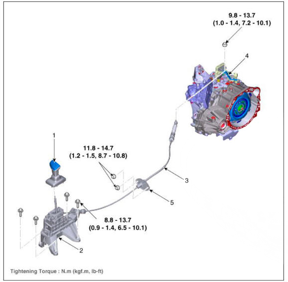
- Shift lever knob & boots assembly
- Shift lever assembly
- Shift cable
- Manual control lever
- Shift cable retainer
Removal
- Turn ignition switch OFF and disconnect the negative (-) batteiy cable.
- Remove the air cleaner assembly and air duct.
(Refer to Engine Mechanical System - "Air cleaner")
- Remove the ECM.
(Refer to Engine Control / Fuel System - "Engine Control Module (ECM)")
- Remove the batteiy and batteiy tray.
(Refer to Engine Electrical System - "Battery")
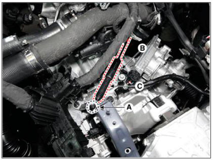
- Remove the shift cable (C) from the cable bracket (B), after loosening the mounting nut (A).
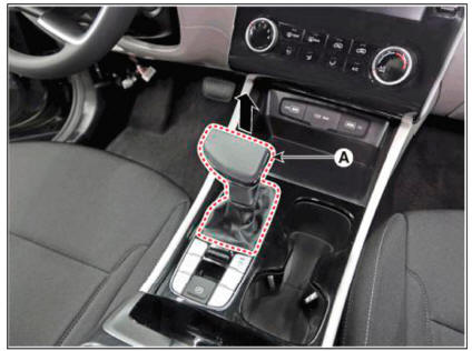
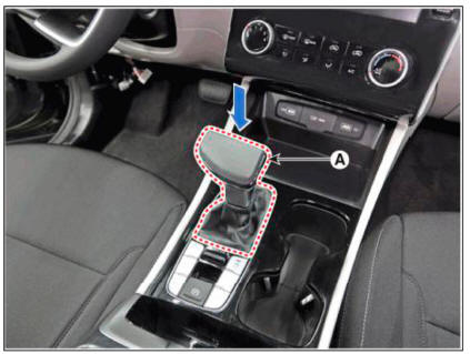
- Remove the shift lever knob & boots (A) pull both of it up.
- Remove the floor console assembly.
(Refer to Body (Interior and Exterior) - "Floor Console")
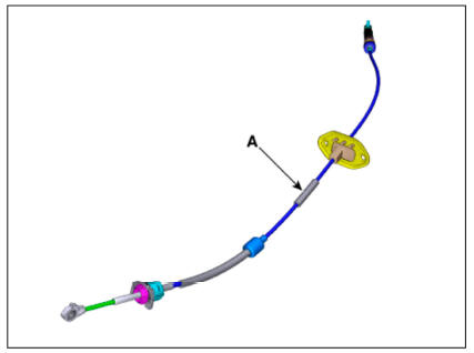
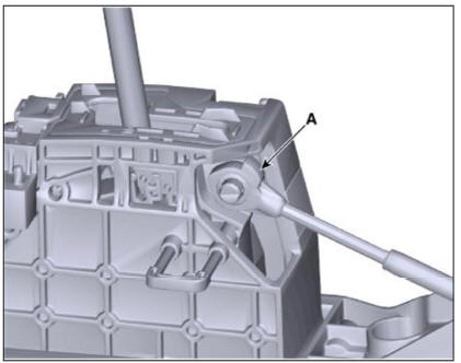
- Disconnect the shift cable (A) after removing the snap pin (B).
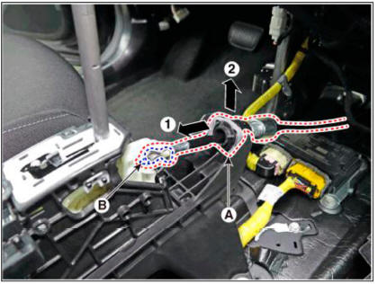
- Remove the retainer (A) by loosening the nuts (B-2ea).
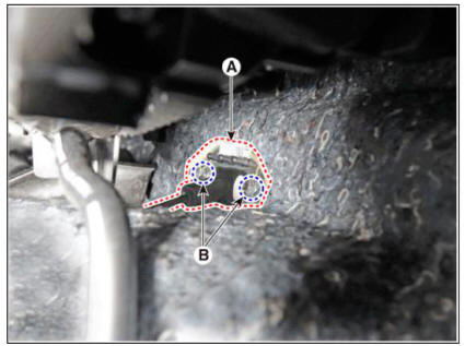
- Remove the shift cable from the vehicle.
Installation
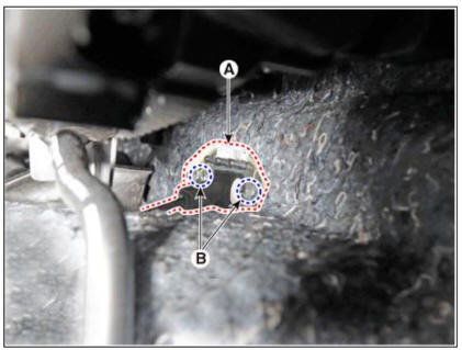
- Install the retainer (A) and then tighten the nut (B-2ea).
Tightening torque : 11.8 - 14.7 N.m (1.2 - 1.5 kgf.m, 8.7 - 10.8 lb-ft)
- Install the shift cable (A) and then fix the snap pin (B).
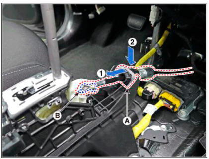
WARNING
- When assembling shift cable, the projection (A) must face
upwards.
- When assembling the snap pin, be careful about the correct direction.
The band portion (A) must point to the front of the vehicle.
The band portion (A) must point outwards.

- Install the floor console assembly.
(Refer to Body - "Floor Console")
- Install the shift lever knob & boots (A).
- Install the shift cable (A) in the cable bracket (B).
- Align the hole (C) in the manual control lever with the "N" position hole (D) of the inhibitor switch and then insert the inhibitor switch guide pin (SST No.:09480-A3800).
- Lightly tighten the nut (E) after connected the shift cable (A) in the manual control lever.
- Push shift cable (A) lightly to "F" direction shown to eliminate free play of shift cable.
- Tighten the nut (E) with the specified torque.
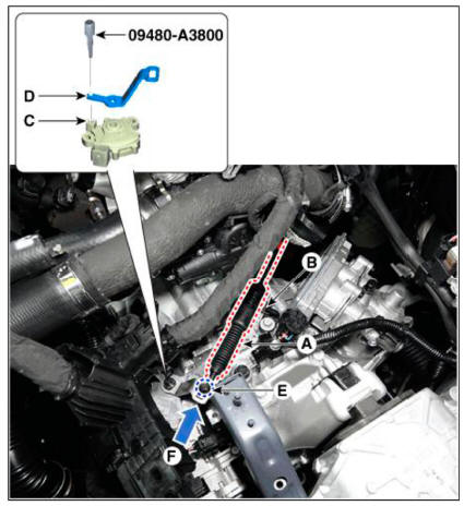
- Remove the inhibitor switch guide pin (SST No.:09480-A3800) from the hole.
- Install the batteiy and tray.
(Refer to Engine Electrical System - "Battery")
- Install the ECM.
(Refer to Engine Control / Fuel System - "Engine Control Module (ECM)")
- Install the air cleaner assembly and air duct.
(Refer to Engine Mechnical System - "Air cleaner")
WARNING
Check that operating surely at each range of the inhibitor switch corresponding to each position of shift lever.
Description
Components location : DCT (Dual Clutch Transmission)
Function
The dual clutch is installed within the transmission.
The dual clutch comprises an odd clutch and an even clutch. The odd clutch transfers and cuts off engine power to the transmission when shifting odd gears.
The even clutch transfers and cuts off engine power to the transmission when shifting even gears.
READ NEXT:
 Dual clutch assembly
Components
Dual clutch assembly
Snap ring
Spline hub
Retaining ring
Removal
Remove the dual clutch transmission from the vehicle.
(Refer to Dual Clutch Transmission Assembly - "DCT (Dual Clutch
Transmission)"
Engagement bearing - Components
Components
Engagement bearing sleeve
Clutch engagement fork
Engagement bearing 1 (Odd)
Engagement bearing 2 (Even)
Dual clutch assembly
Snap ring
Spline hub
Retaining ring
Removal
Remove the dual clutch transmission from
DCT (Dual Clutch Transmission) System (SBW)
Troubleshooting
Specifications
Clutch Actuator
Gear Actuator
Inhibitor Switch
Type: Combination of output signals from 4 terminals
Specifications
Input speed sensor
Tightening Torques
Lubricants
SEE MORE:
Electric Exhaust Gas Re-circulation (EEGR) Control Valve
Description
The Electric EGR Control Valve is installed in between the EGR cooler and the
exhaust line and is a
solenoid valve. This valve controls EGR (Exhaust Gas Recirculation) amount by
the ECM's duty
control signal depending on engine
Front seat shield inner cover/ Front seat back cover
Component Location
Front seat shield inner cover
Replacement
WARNING
When removing with a flat-tip screwdriver or remover, wrap
protective tape around the tools to
prevent damage to components.
Put on gloves to prevent hand inj
Information
- Home
- Hyundai Tucson - Fourth generation (NX4) - (2020-2023) - Owner's Manual
- Hyundai Tucson - Fourth generation (NX4) - (2020-2023) - Workshop Manual
