Hyundai Tucson: Dual clutch assembly
Components
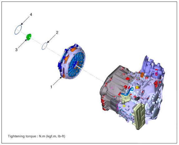
- Dual clutch assembly
- Snap ring
- Spline hub
- Retaining ring
Removal
- Remove the dual clutch transmission from the vehicle.
(Refer to Dual Clutch Transmission Assembly - "DCT (Dual Clutch Transmission)")
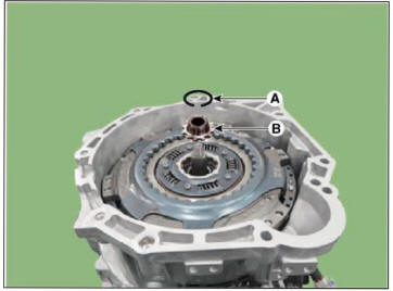
- Remove the retaining ring (A) and then removing the spline hub (B).

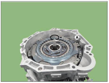
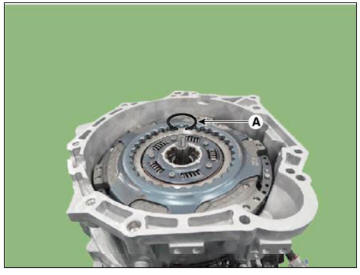
- Remove the snap ring (A).
WARNING
- The snap ring can deform when it removed by forced removal and can't reuse it.
- If it's difficult to remove the snap ring for stuck, release the stuck by using a rubber hammer with a center cylinder of dual clutch installer (09430-2A240) and then remove the snap ring.
- Be careful to damage dual clutch assembly support bearing rubber seal.
WARNING
l)When removing is not possible due to snap ring jamming,
place the center cylinder (09430-2A240) and hit it with a
rubber hammer. When it looses, remove it.
2)In case of the dual clutch reuse, make sure not to damage the dual
clutch support bearing rubber seal (A) when
removing the snap ring. 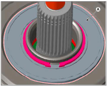
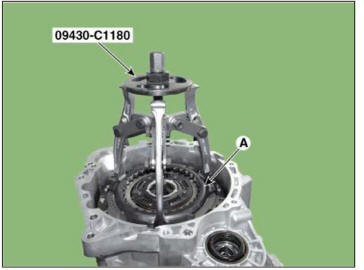
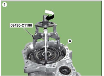
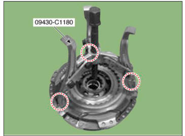
- Remove the dual clutch assembly (A).
1)Attach the special tool (09430-C1180) to the dual clutch assembly and remove it with a wrench or a spanner.
2)Use a special tool (09430-C 1180) to detach the dual clutch from the transmission housing.
* When detaching the dual clutch from the transmission housing, make sure not to drop the dual clutch.
Installation
WARNING
- Remove the dust and foreign matters from the input shaft spline (A) and shaft (B).
* Do not use steel soles and sandpapers. WD40 and anti-corrosive
lubricant. (It could cause a corrosion of the rubber or
oil seals.) 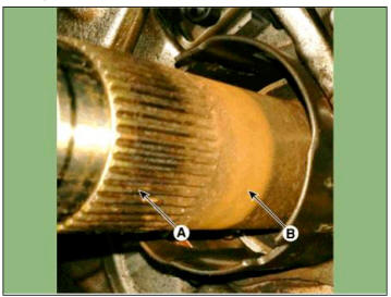
2)Check the grease on the input shaft spline part (A). If there is no grease, apply it to the 10mm point from the each end of the spline.
* Grease overspraying may result excessive scattering and this may cause the clutch to slip.
Specified grease : Extreme pressure grease for vehicle
Quantity : 0.15 - 0.25g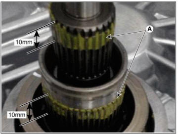
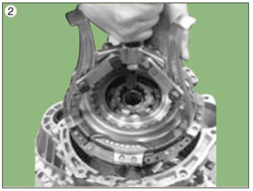
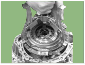
- Fix the special tool (09430-C 1180) to the dual clutch assembly at three places at 120-degree intervals, then move to the top of the housing.
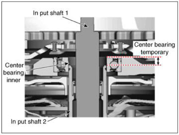
- Assemble the dual clutch to the input shaft 2 temporarily.
WARNING
Dual clutch temporary assembly condition
- In the input shaft 2. the center bearing inner ring should be properly and temporarily inserted.
- When th clutch is press-fitted in an unstable temporary
assembly, it may cause damage to the clutch.
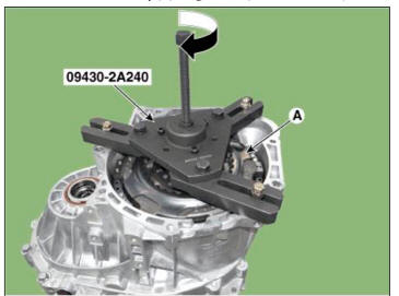
- Install the SST (No.:09430-2A240) on the support bearing within the dual clutch assembly (A).

- Install the SST (No. : 09430-2A240) on the clutch housing side.
- Install the dual clutch assembly (A) using the SST (No. : 09430-2A240).
- Install the snap ring (A).
WARNING
After tightening the snap ring (A), see if it can properly rotates
to the right or the left. 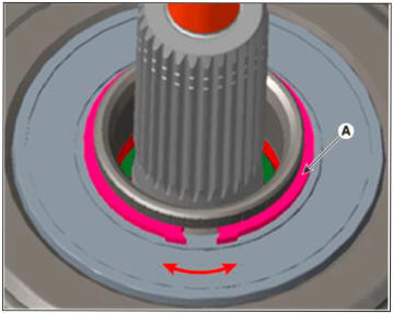
- Install the spline hub (B) and the install the retaining ring (A).
- Install the dual clutch transmission in the vehicle.
(Refer to Dual Clutch Transmission Assembly - "DCT (Dual Clutch Transmission)")
- Perform the work procedures for abrasion compensation reset after installing the new dual clutch assembly.
(Refer to Clutch Actuator & TCM Assembly - "Adjustment")
- Perform the clutch touch point learning procedure using the GDS after replacing the dual clutch assembly.
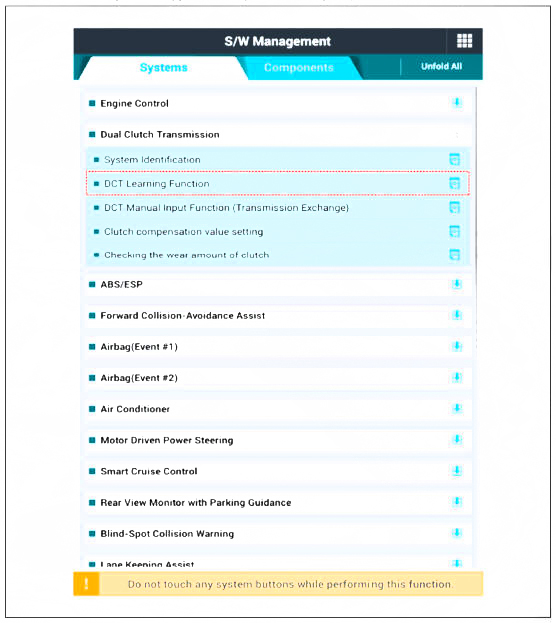
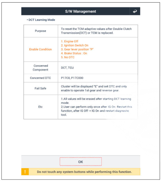
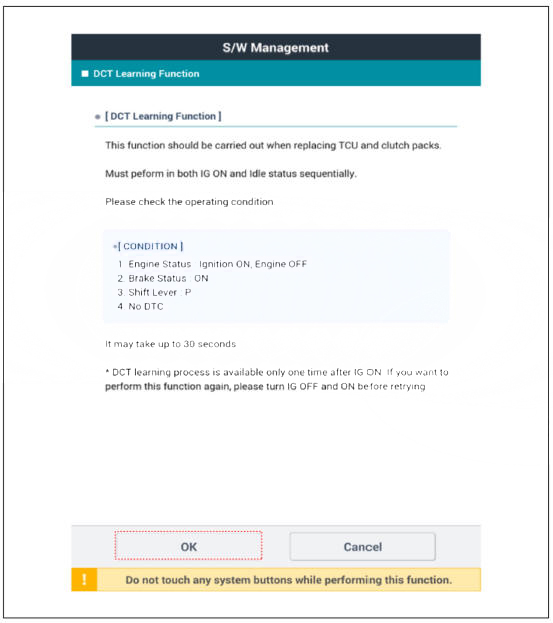
WARNING
- Even if you removed and reinstalled the clutch actuator, be sure to perform the touch point learning.
- If you have replaced the dual clutch assembly or clutch actuator, be sure to perform the touch point learning.
READ NEXT:
 Engagement bearing - Components
Components
Engagement bearing sleeve
Clutch engagement fork
Engagement bearing 1 (Odd)
Engagement bearing 2 (Even)
Dual clutch assembly
Snap ring
Spline hub
Retaining ring
Removal
Remove the dual clutch transmission from
DCT (Dual Clutch Transmission) System (SBW)
Troubleshooting
Specifications
Clutch Actuator
Gear Actuator
Inhibitor Switch
Type: Combination of output signals from 4 terminals
Specifications
Input speed sensor
Tightening Torques
Lubricants
DCT (Dual Clutch Transmission) System (SBW)- Removal
Components
DCT (Dual Clutch Transmission) assembly
DCT support bracket
Roll rod support bracket
Removal
Turn ignition switch OFF and disconnect the negative (-) battery cable.
Remove the air cleaner assembly and air duct.
SEE MORE:
Column & Housing Noise Repair Guide
R-MDPS Warning lamp Diagnosis Guide
Inspection Items per DTC
Checking Connectors and Wiring
Checking Connectors and Wiring.
Check for damage, push-back, or improper connection in each connector and
wiring.
(1) Check th
Lane Keeping Assist (LKA)
Lane Keeping Assist is designed to help
detect lane markings (or road edges)
while driving over a certain speed. Lane
Keeping Assist will warn the driver if the
vehicle leaves the lane without using the
turn signal, or will automatically assist
Information
- Home
- Hyundai Tucson - Fourth generation (NX4) - (2020-2023) - Owner's Manual
- Hyundai Tucson - Fourth generation (NX4) - (2020-2023) - Workshop Manual
