Hyundai Tucson: Front Suspension System- Replacement
Replacement
WARNING
When lifting a vehicle using a lift, be careful not to damage the lower parts of the vehicle (floor under cover, fuel filter, fuel tank, canister).
(Refer to General Information - "Lift Point")
- Loosen the front wheel nuts slightly.
Raise the vehicle, and make sure it is securely supported.
- Remove the front wheel and tire.
(Refer to Suspension System - "Wheel")
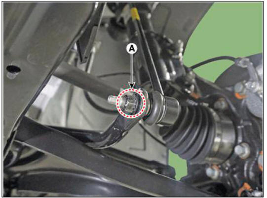
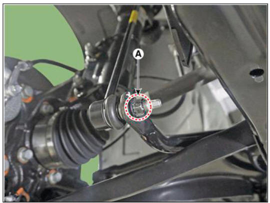
- Loosen the stabilizer link mounting nut (A).
Tightening torque : 98.1 - 117.7 N.m (10.0 - 12.0 kgf.m, 72.3 - 86.8 lb-ft)
WARNING
- When loosening the nut. fix the outer hexagon of stabilizer bar link.
- Be careful not to damage the stabilizer link boots.
LH
RH
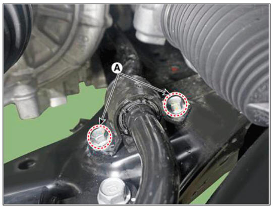
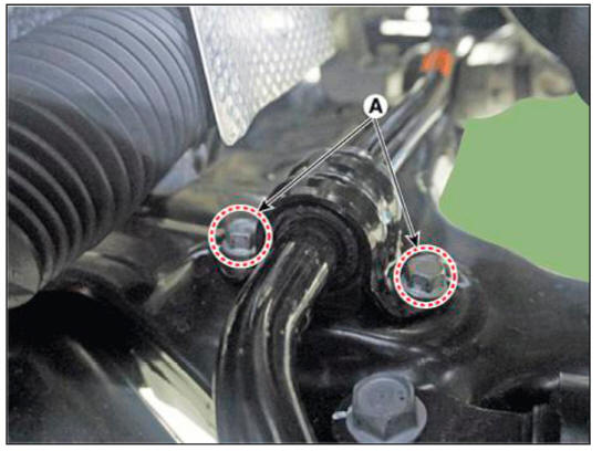
- Remove the stabilizer bar after loosening the mounting bolts (A).
Tightening torque : 49.0 - 63.7 N.m (5.0 - 6.5 kgf.m, 36.2 - 47.0 lb-ft)
LH
RH
Inspection
- Check the bushing for wear and deterioration.
- Check the front stabilizer link ball joint for damage.
Installation
- To install, reverse the removal procedures.
- Check the alignment.
(Refer to Suspension System - "Alingment")
Removal
WARNING
When lifting a vehicle using a lift, be careful not to damage the lower parts of the vehicle (floor under cover, fuel filter, fuel tank, canister).
(Refer to General Information - "Lift Point")
- Loosen the front wheel nuts slightly.
Raise the vehicle, and make sure it is securely supported.
- Remove the front wheel and tire.
(Refer to Suspension System - "Wheel")
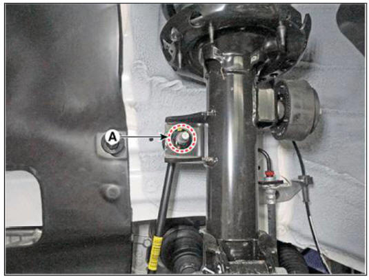
- Remove the stabilizer link bar link from the front stmt after loosening the mounting nut (A).
Tightening torque : 98.1 - 117.7 N.m (10.0 - 12.0 kgf.m. 72.3 - 86.8 lb-ft)
WARNING
- When loosening the nut. fix the outer hexagon of stabilizer bar link.
- Be careful not to damage the stabilizer link boots.
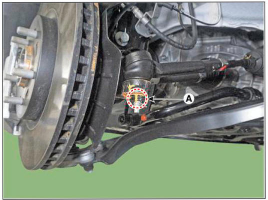
- Loosen the tie rod end ball joint nut (A).
Tightening torque : 98.0 - 117.6 N.m (10.0 - 12.0 kgf.m. 72.3 - 86.7 lb-ft)
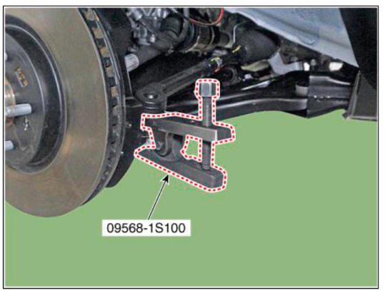
- Remove the tie rod end ball joint using the SST (09568-IS 100).
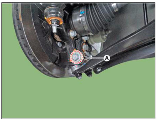
- Loosen the front lower arm mounting bolt and nut (A).
Tightening torque : 98.0 - 117.6 N.m (10.0 - 12.0 kgf.m. 72.3 - 86.7 lb-ft)
- Remove the lower arm from the knuckle by using the SST (09568-4R100).
(1) Install the support bolt (A) from lower arm bolt hole.
(2) Install the support body (B) from front axle.
(3) Tighten the bolt (C).

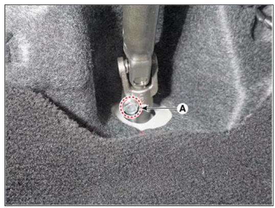
- Separate the universal joint from the steering gear box after universal joint mounting bolt (A).
Tightening torque : 53.9 - 58.8 N.m (5.5 - 6.0 kgf.m. 39.8 - 43.4 lb-ft)
WARNING
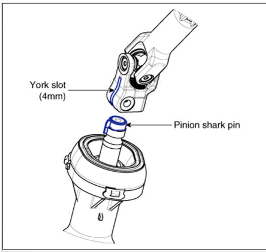
- Do not reuse the bolt.
- Lock the steering wheel in the straight ahead position to prevent the damage of the clock spring inner cable.
- Assemble so that the universal joint hole is inserted matching
the cut surface of the pinion shaft shark pin
- Remove the under cover.
(Refer to Engine Mechanical System - "Engine Room Under Cover")
- Disconnect the R-MDPS main connector (A). R-MDPS Type only

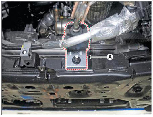
- Remove the muffler rubber hanger (A) from the sub frame after loosening the mounting nut.
Tightening torque : 19.6 - 25.5 N.m (2.0 - 2.6 kgf.m, 14.5 - 18.8 lb-ft)
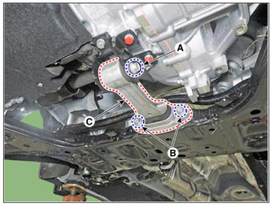
- Remove the roll rod bracket (C) after loosening the bolt (A), (B).
Tightening torque :
(A): 107.9 - 127.5 N.m (11.0 - 13.0 kgf.m, 79.6 - 94.0 lb-ft)
(B): 49.0 - 63.7 N.m (5.0 - 6.5 kgf.m, 36.2 - 47.0 lb-ft)
WARNING
Set a transmission jack for safety.
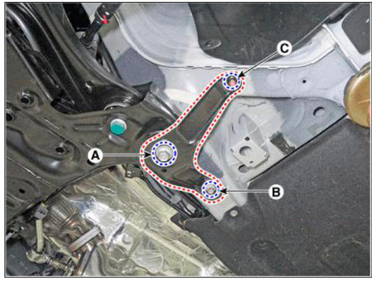
- Remove the sub frame stay after loosening the mounting bolts (A, B) and nut (C).
Tightening torque :
(A): 176.5 - 196.1 N.m (18.0 - 20.0 kgf.m, 130.2 - 144.7 b-ft)
(B): 44.1 - 53.9 N.m (4.5 - 5.5 kgf.m, 32.5 - 39.8 lb-ft)
(C): 44.1 - 53.9 N.m (4.5 - 5.5 kgf.m, 32.5 - 39.8 lb-ft)
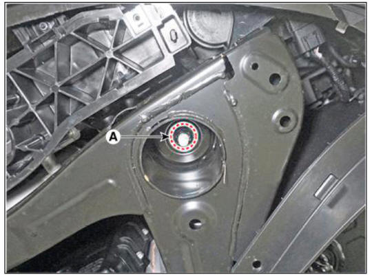
- Loosen the sub frame mounting nuts (A).
Tightening torque : 176.5 - 196.1 N.m (18.0 - 20.0 kgf.m. 130.2 - 144.7 b-ft)
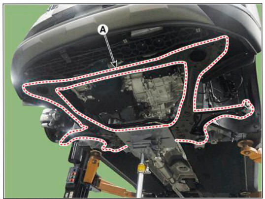
- Remove the sub frame.
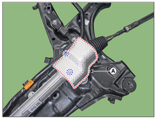
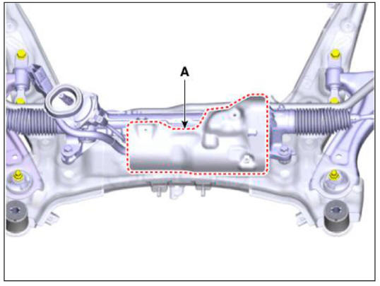
- Remove the heat protector (A).
Tightening torque : 7.8 - 11.8 N.m (0.8 - 1.2 kgf.m, 5.8 - 8.7 lb-ft)
C-MDPS
R-MDPS
- Remove the steering gearbox (A) from the front sub frame after loosening the mounting bolts.
Tightening torque : 107.9 - 127.5 N.m (11.0 - 13.0 kgf.m. 79.6 - 94.0 lb-ft)
C-MDPS
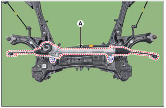
R-MDPS
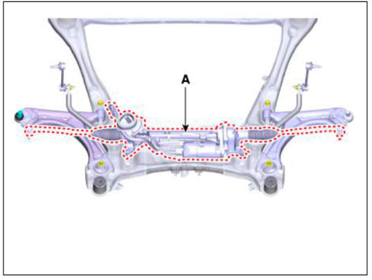
- Remove the stabilizer bar (A) from the sub frame after loosening the mounting bolts.
Tightening torque : 49.0 - 63.7 N.m (5.0 - 6.5 kgf.m, 36.2 - 47.0 lb-ft)
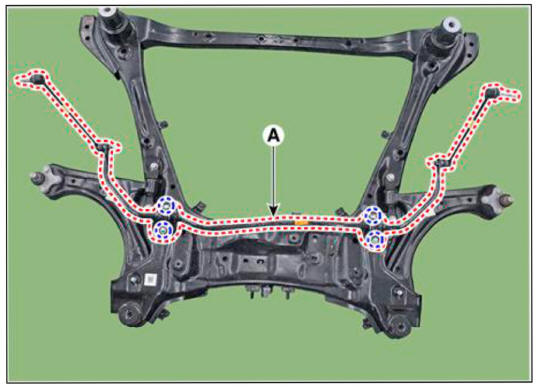
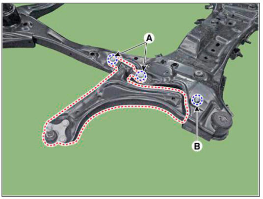
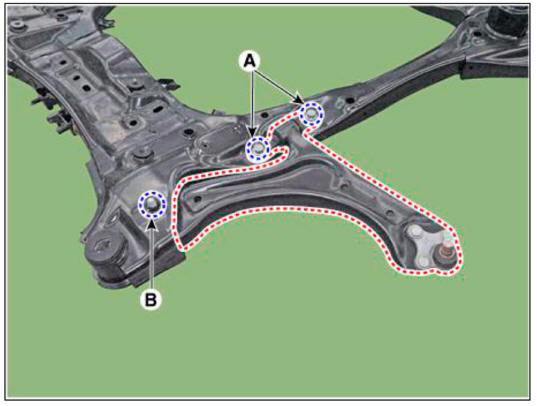
- Remove the front lower arm after loosening the mounting bolts (A. B).
Tightening torque :
(A): 156.9 - 176.5 N.m (16.0 - 18.0 kgf.m, 115.7 - 130.2 lb-ft)
(B): 156.9 - 176.5 N.m (16.0- 18.0 kgf.m. 115.7- 130.2 lb-ft)
LH
RH
Installation
- To install, reverse the removal procedures.
- Check the alignment.
(Refer to Suspension System - "Alingment")
READ NEXT:
 Rear Suspension System - Components
Components
2WD
Rear shock absorber
Rear lower arm
Rear stabilizer bar
Rear sub frame
Rear upper arm
Rear assist arm
Trailing arm
4WD
Rear shock absorber
Rear lower arm
Rear stabilizer bar
Rear differential carrier
Rear shock absorber
Components
Lock nut
Insulator assembly
Dust cover
Rear shock absorber
Removal
WARNING
When lifting a vehicle using a lift, be careful not to damage the
lower parts of the vehicle (floor under
cover, fuel filter, fuel tank, canis
SEE MORE:
Function Of Safety Power Window
Operation
When driver door power window auto-up switch is operated, safety function is
activated.
Safety function condition
When detect the force of 100N (using the lON/mm spring) during the window
rising, window is
reversed.
Length
Repair procedures
Compession Pressure Inspection
WARNING
If the there is lack of power, excessive oil consumption or poor
fuel economy, measure the compression
pressure.
Start the engine and turn the coolant temperature to 80 - 95 ºC and stop.
Remove the
Information
- Home
- Hyundai Tucson - Fourth generation (NX4) - (2020-2023) - Owner's Manual
- Hyundai Tucson - Fourth generation (NX4) - (2020-2023) - Workshop Manual
