Hyundai Tucson: Run out inspection
- Jack up the vehicle.
- Measure the wheel Run-out by using a dial indicator as illustration below.
- If measured value exceeds the standard value, replace the wheel.
Adjustment
When using a commercially available computerizedwheel alignment equipment to inspect the front wheelalignment, always position the vehicle on a levelsurface with the front wheels facing straight ahead.
Prior to inspection, make sure that the frontsuspension and steering system are in normaloperating condition and that the tires are inflated tothe specified pressure.
Front
Toe
Total: 0.1 º +- 0.2 º
Individual: 0.05º +-0.1º

Tightening torque : 49^0 - 53.9 N.m (5.0 - 5.5 kgf.m, 36.2 - 39.8 lb-ft)
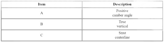
Camber
Camber refers to the tilt of the center of the wheel.
Camber angle : -0.5º +- 0.5º
Caster
Caster is pre-set at the factory and doesn't need to be adjusted. If the caster is not within the standard value, replace the bent or damaged parts.
Caster : 4.85º +- 0.5º
Rear
Toe
Toe
Total: 0.2º +- 0.2 º
Individual: 0.1º +-0.1º
Camber
Camber angle : -1.2º +-0.5º
READ NEXT:
 TREAD Lamp
Tire Under Inflation / Leak Warning.
Turn on condition
When tire pressure is below allowed threshold
When rapid leak is detected by the sensor.
Indicates that tire needs to be re-inflated to placard pressure /
repaired.
Tire Pressure Monitoring System - Replacement
Remove the tire.
(Refer to Suspension System - "Wheel")
Remove the screw with torx driver (A).
WARNING
When installing the bead brake, make sure that it does not come
in contact with the TPMS sensor.
Be careful no
SEE MORE:
Controller
Component
Connector Pin Function
Replacement
Disconnect the negative (-) battery terminal.
Remove the front monitor.
(Refer to Body Electrical System - "Front Monitor")
Remove the heater & AJC control unit (A).
General Information
Description
System Description
Advanced Driver Assistance System (ADAS) analyzes the exterior environment of
a vehicle and driver status to provide
visibility / display / guide / warning for driving and parking.
System Configuration
Sp
Information
- Home
- Hyundai Tucson - Fourth generation (NX4) - (2020-2023) - Owner's Manual
- Hyundai Tucson - Fourth generation (NX4) - (2020-2023) - Workshop Manual
