Hyundai Tucson: TREAD Lamp
- Tire Under Inflation / Leak Warning.

- Turn on condition
- When tire pressure is below allowed threshold
- When rapid leak is detected by the sensor.
- Indicates that tire needs to be re-inflated to placard pressure / repaired.
- Turn off condition
- Under-inflation ; When tire pressure is above (warning threshold + hysteresis).
- Rapid Leak ; When tire pressure is above (leak warning threshold).
DTC Warning
- Turn on condition
- When the system detects a fault that is external to the receiver/ sensor.
- When the system detects a receiver fault.
- When the system detects a sensor fault.
- Turn off condition
- f the fault is considered as 'critical', then the lamp is held on
throughout the current Ignition
cycle (even if the DTC has been demoted). This is because it is important to
bring the problem to
the drivers attention. On the following Ignition cycle, the demotion
conditions will be rechecked.
If the demotion conditions occur, the lamp will be turned off. It will be held on until DTC demotion checking is completed.
- Non critical' faults are those that can occur temporarily e.g. vehicle battery under voltage. The lamp is therefore turned off when the DTC demotion condition occurs.
WARNING
If the vehicle starts within 19 minutes after the replacement of the wheel of the stopped vehicle, the TPMS Malfunction Indicator on the instrument cluster illuminates.
- The above symptom is due to communication failure between the BCM and the replaced TPMS ID.
- This communication failure indicator turns off in 19 minutes
after the vehicle stops through
the BCM's automatic learning process of TPMS ID.
(When driving the vehicle after stopping for over 19 minutes, the indicator turns off automatically.)
System Fault
- General Function
- The system monitors a number of inputs across time in order to determine that a fault exists.
- Faults are prioritized according to which has the most likely cause.
- Maximum fault store is equal to 15.
- Certain faults are not covered through DTC. The main ones are :
a. Sensor thermal shutdown (over 257ºF / 125ºC).
b. Ignition Line stuck ; requires observation of lamps at Ignition ON to diagnose.
Components Location
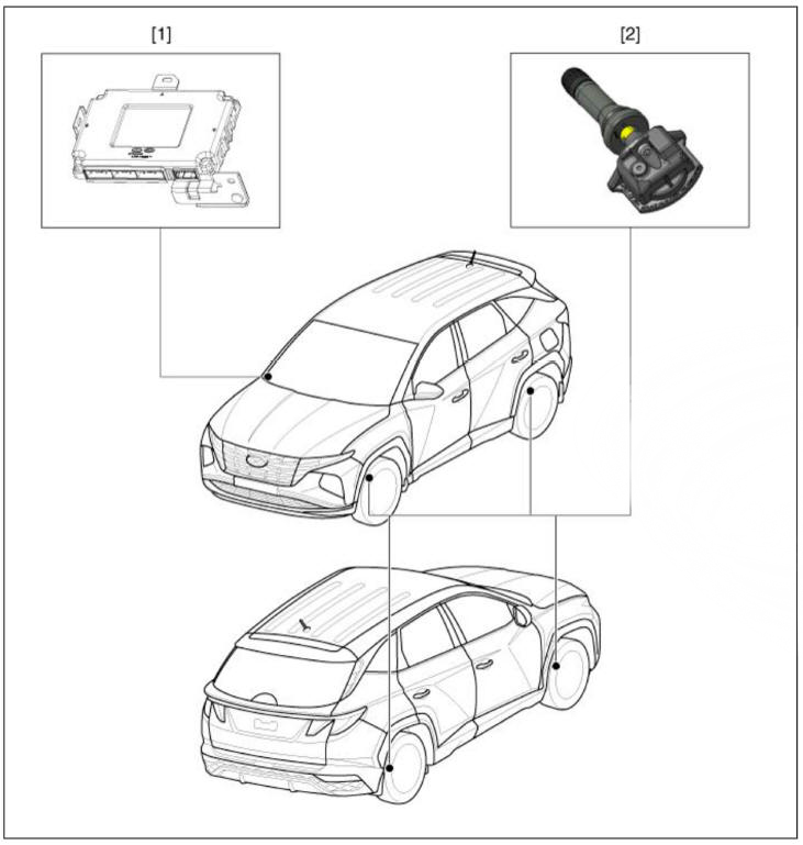
- Receiver
- TPMS Sensor
Description

- Driving state
Sensor transmissions occur every 1 minutes and pressure is measured every 15 seconds.
- Stationary state
Sensor transmissions does not occur and pressure is measured every 60 seconds.
- Auto learning status
When driving after stopping more than 15 minutes , sensor transmissions occur eveiy 33 seconds and pressure is measured every 10.8 seconds.
- Off status
The TPMS sensor is not operated.
Due to stock status, does not measured pressure, temperature, battery status.
- Alert State :
When a 2 psi change in pressure from the last transmission occurs, transmit tire information immediately.
The pressure is measured every 2 seconds.
READ NEXT:
 Tire Pressure Monitoring System - Replacement
Remove the tire.
(Refer to Suspension System - "Wheel")
Remove the screw with torx driver (A).
WARNING
When installing the bead brake, make sure that it does not come
in contact with the TPMS sensor.
Be careful no
Diagnostic Procedure Using a Diagnostic
Instrument
The following section describes how to diagnose faults using a diagnostic
instrument.
Connect the diagnostic instalment to the self-diagnostic connector
(16-pin) beneath the crash pad on the side of driver's
seat, and then
TPMS Receiver : BCM(body control module) integrated management
Description
Mode
(1) Virgin State
The receiver as a sole part is shipped in this state. Replacement parts
should therefore arrive
in this state.
In this state, there is no Auto-Location, no sensor wake-up, no sensor
monitorin
SEE MORE:
Clock
These hooks are not designed to hold
large or heavy items.
WARNING
Do not hang other objects such
as hangers or hard objects except
clothes. Also, do not put heavy, sharp
or breakable objects in the clothes
pockets. In an accident or when th
Wiper blades
Blade inspection
Contamination of either the windshield
or the wiper blades with foreign matter
can reduce the effectiveness of the
windshield wipers.
Common sources of contamination are
insects, tree sap, and hot wax treatments
used by some
Information
- Home
- Hyundai Tucson - Fourth generation (NX4) - (2020-2023) - Owner's Manual
- Hyundai Tucson - Fourth generation (NX4) - (2020-2023) - Workshop Manual
