Hyundai Tucson: Piston Pin - Disassembly
WARNING
- Use fender covers to avoid damaging painted surfaces.
- To avoid damage, unplug the wiring connectors carefully while holding the connector portion.
WARNING
- Mark all wiring connector and hoses to avoid misconnection.
- To release the fuel system pressure before removing the engine assembly, start the engine without fuel pump relay. Then, switch "OFF" the ignition when engine stops.
- Turn the crankshaft pulley so that the No. 1 piston is at top dead center.
- Remove the piston and connecting rod assembly.
(Refer to Cylinder Block - "Piston and Connecting Rod")
- Remove the air conditioning compressor.
(Refer to Heating, Ventilation and Air Conditioning - "Compressor")
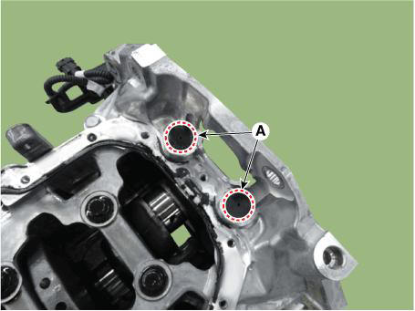
- Remove the rear caps (A).
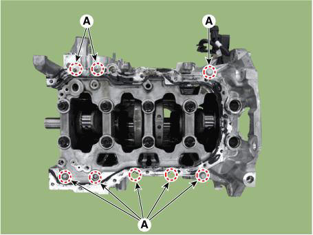
- Remove the lower crankcase.
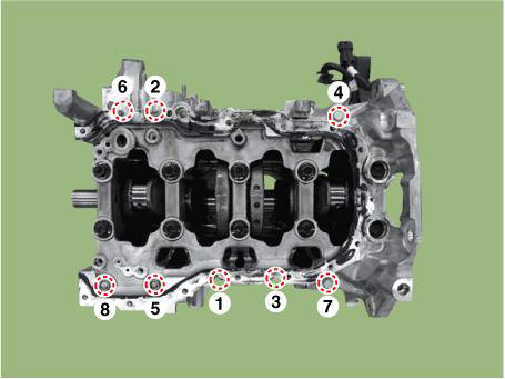
(1) Remove the lower crankcase mounting bolts (A).
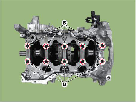
(2) Remove the crankshaft bearing cap bolts (B).
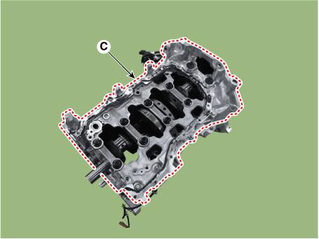
(3) Remove the lower crankcase (A).
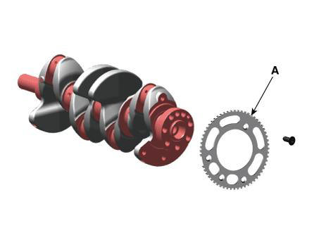
- Remove the crankshaft position sensor wheel (A).
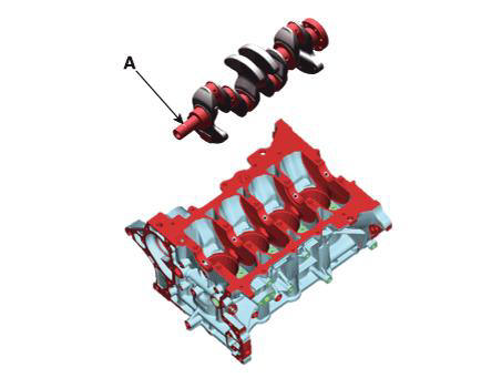
- Lift the crankshaft (A) out of the engine block, being careful not to damage journals.
Piston Pin- Inspection
- Check the crankshaft bearing oil clearance.
(1) Clean each main journal and lower bearing with a clean shop towel.
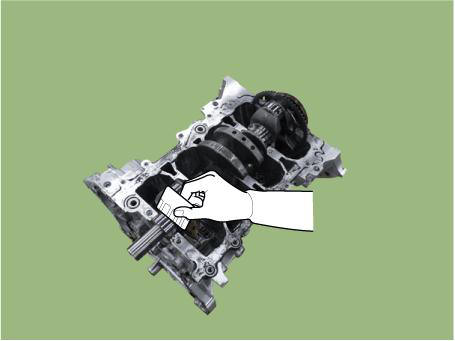
(2) Place one strip of plastcigauge across each main journal.
(3) Reinstall the bearing caps with their lower bearings, then tighten the bolts.
Tightening torque : Crank lower case mounting bolts : 18.6 - 23.5 N.m (1.9 - 2.4 kgf.m, 13.7 - 17.4 lb-ft)
Bearing cap mounting bolts : 27.5 - 31.4 N.m (2.8 - 3.2 kgf.m, 20.3 - 23.1 lb-ft) + 118 - 122º
Crank lower case mounting bolts
Bearing cap mounting bolts

WARNING
Do not turn the crankshaft.
(4) Remove the lower crankcase, and measure the widest part of the plasticgauge.
Bearing oil clearance : 0.030 - 0.048 mm (0.0012 - 0.0019 in.)
(5) If the plasticgauge measures too wide or too narrow, remove the upper and lower bearing and then install a new bearings with the same color mark (select the color as shown in the next column). Recheck the oil clearance.
WARNING
Do not file, shim, of scrape the bearings or the caps to adjust clearance.
(6) If the plasticgauge shows that the clearance is still incorrect, try the next larger or smaller bearing (the color listed above or below that one), and check clearance again.
WARNING
- If the plasticgauge shows that the clearance is still incorrect, try the next larger or smaller bearing (the color listed above or below that one), and check clearance again.
- If the marks are indecipherable because of an accumulation of dirt and dust, do not scrub them with a wire brush or scraper. Clean them only with solvent or detergent.
READ NEXT:
 Cylinder Block Crankshaft Journal Bore Mark Location
Letters have been stamped on the side surface of the block as a mark for the
size of each of the 5 main
journal bores.
Use them, and the numbers or letters stamped on the crank (marks for main
journal size), to choose the
correct bearings.
Piston Pin - Reassembly
WARNING
Thoroughly clean all parts to assembled.
Before installing the parts, apply fresh engine oil to all
sliding and rotating surfaces.
Always use new gaskets, O-ring and oil seals.
Install the crankshaft position sensor wheel
Cylinder Block/ Disassembly/ Inspection/ Reassembly
WARNING
Use fender covers to avoid damaging painted surfaces.
To avoid damage, unplug the wiring connectors carefully while
holding the connector portion.
WARNING
Mark all wiring connector and hoses to avoid misconnection.
To releas
SEE MORE:
Front Muffler
Removal and Installation
Disconnect the battery negative terminal.
Disconnect the oxygen sensor connector (A).
Remove the engine room rear under cover (A).
Tightening torque :
7.8 - 11.8 N.m (0.8 - 1.2 kgf.m, 5.8 - 8.7 lb-ft)
Oil cooler pipe
Remove the heater pipe
Disconnect the oil cooler hose (A) from the ITM.
Disconnect the oil cooler hose (A) from the oil cooler.
Rmove the oil cooler pipe (A) after loosening the mounting bolts.
Tightening torque :
9.8 - 1
Information
- Home
- Hyundai Tucson - Fourth generation (NX4) - (2020-2023) - Owner's Manual
- Hyundai Tucson - Fourth generation (NX4) - (2020-2023) - Workshop Manual
