Hyundai Tucson: Coupling Assembly - Description
Hyundai Tucson - Fourth generation (NX4) - (2020-2023) - Workshop Manual / Wheel Drive (4WD) System / Coupling Assembly / Coupling Assembly - Description
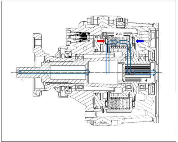
Component Location
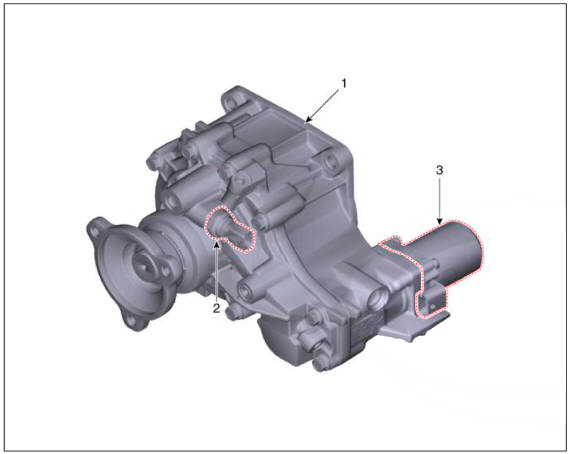
- Coupling assembly
- Pressure sensor
- Oil hydraulic motor
Description
4\VD ECU processes signals from various sensors and determines the current road and driving conditions. The ECU then utilizes this information to implement precision control over the 4WD coupling's multi-plate clutch and variably adjust the amount of torque delivered tothe rear wheels.
Four Wheel Drive (4WD) transfer mode selection
- AUTO MODE:
- When driving in 4WD AUTO mode, the vehicle operates similar to conventional 2WD vehicles under normal operating conditions. However, if the system determines that there is a need for the 4WD mode, the engine's driving power is distributedto all four wheels automatically without driver intervention.
- When driving 011 normal roads and pavement, the vehicle moves similar to conventional 2WD vehicles.
- LOCK MODE:
- This mode is used for climbing or descending sharp grades, off-road driving, driving on sandy and muddy roads, etc., to maximize traction.
- However, binding may occur in LOCK MODE when circling and it does not operate when the vehicle speed is over 60 km/h.
Electronic Coupling - 4WD Control (By Driving Condition)
- Cruising (Auto Mode)
- Power is delivered mostly to the front wheels.
- Cornering (Auto Mode)
- Adjusts the amount of power to the rear wheels based on the turning radius and cornering speed.
- Wheel Slip (Auto Mode)
- f one or both of the front wheels lose traction, the system transfers an appropriate amount of power to the rear wheels based 011 the slip amount at the front wheels.
Operation
Electronic Coupling
- The power is delivered in the following order: Transmission -> Transfer -> Propeller shaft
- AWD ECU calculates the necessary amount of rear-wheel torque and sends the corresponding driving current to the actuator (electronic motor and hydraulic pump).
- The piston operates by the oil pressure and the friction is generated. Then, the clutch is engaged.
- The power is delivered to the differential by the engaged clutch and the driving power is generated in to the rear wheel.
READ NEXT:
 Coupling Assembly- Removal
Inspection
WARNING
All units are filled up with coupling fluid (ultra-low viscosity ATF)
prior to shipping. Inspection, fillup,
and replacement of coupling fluid is therefore not necessary (zero maintenance,
lifetime fluid).
Removal
WARNING
Coupling Assembly- Installation
To install, reverse the removal procedures.
WARNING
Smear the splines (A) with molybdenum type high pressure grease.
When install the coupling, be careful not to damage the oil
seal (B).
After replacing the coupling, reset the 4
Oil Hydraulic Motor (Actuator) Inspection Procedure
Removal
Remove the coupling assembly.
(Refer to 4 Wheel Drive (4WD) System - "Direct Electro Hydraulic Actuator
Coupling")
Keep going perpendicular state after remove the coupling assembly.
WARNING
Keep going perpend
SEE MORE:
Rear Axle Assembly- Removal- 2WD
Components
Rear brake disc
Rear hub assembly
Dust cover
Rear carrier assembly
Removal
2WD
WARNING
When lifting a vehicle using a lift, be careful not to damage the
lower parts of the vehicle (floor under cover,
fuel filter, fue
Oil Hydraulic Motor (Actuator) Inspection Procedure
Removal
Remove the coupling assembly.
(Refer to 4 Wheel Drive (4WD) System - "Direct Electro Hydraulic Actuator
Coupling")
Keep going perpendicular state after remove the coupling assembly.
WARNING
Keep going perpend
Information
- Home
- Hyundai Tucson - Fourth generation (NX4) - (2020-2023) - Owner's Manual
- Hyundai Tucson - Fourth generation (NX4) - (2020-2023) - Workshop Manual
