Hyundai Tucson: Connecting Rod
Inspection
- Check the side clearance between piston and connecting rod.
Using feeler gauge, measure the side clearance while moving the connecting rod back and forth.
Side clearance
Standard : 0.1 - 0.25 mm (0.0039 - 0.0098 in.)
Maximum : 0.35 mm (0.0138 in.)

- If out-of-tolerance, install a new connecting rod.
- If still out-of-tolerance after connecting rod replacement, replace the crankshaft.
- Check the connecting rod bearing oil clearance.
(1) Check the match marks on the connecting rod and cap are aligned to ensure correct reassembly.
(2) Remove the 2 connecting rod cap bolts.
(3) Remove the connecting rod cap and lower bearing.
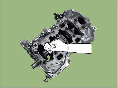
(4) Clean the crankshaft pin journal and bearing.
(5) Place a plasticgauge across the crankshaft pin journal.
(6) Reinstall the lower bearing and connecting rod cap, and torque the bolts.
Tightening torque : 17.7 - 21.6 N.m (1.8 - 2.2 kgf.m, 13.0 - 15.9 lb-ft) + 68º - 72º
WARNING
Do not turn the crankshaft.
(7) Remove the connecting rod cap.
(8) Measure the plasticgauge at its widest point.
Bearing oil clearance : 0.037 - 0.055 mm (0.0015 - 0.0022 in.)
(9) If the measurement from the plasticgauge is too wide or too narrow, remove the upper and lower bearing and then install a new bearings with the same color mark.
Recheck the oil clearance.
WARNING
Do not file, shim, of scrape the bearings or the caps to adjust clearance.
(10) If the plasticgauge shows the clearance is still incorrect, try the next larger or smaller bearing. Recheck the oil clearance.
WARNING
- If the proper clearance cannot be obtained by using the appropriate larger or smaller bearings, replace the crankshaft and start over.
- If the marks are indecipherable because of an accumulation of dirt and dust, do not scrub them with a wire brush or scraper. Clean them only with solvent or detergent.
Connecting Rod Identification Mark
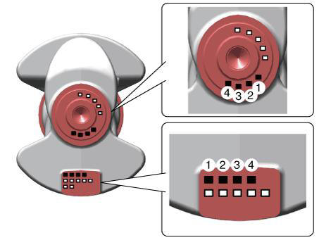
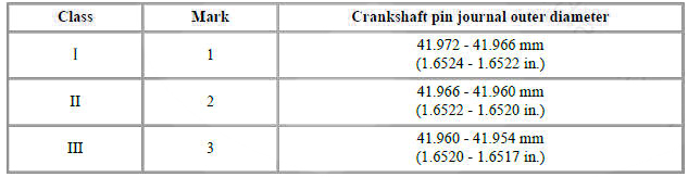
Identification Of Crankshaft Pin Outside Diameter
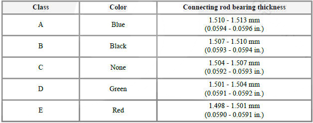
Connecting Rod Bearing Identification Mark
Discrimination of Connecting Rod Bearing
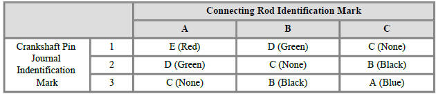
(11) Use the bearing selection table below to select a suitable connecting rod bearing.
Connecting Rod Bearing Selection Table
- Check the connecting rods.
(1) When reinstalling, make sure that cylinder numbers put on the connecting rod and cap at disassembly match.
When a new connecting rod is installed, make sure that the notches for holding the bearing in place are on the same side.
(2) Replace the connecting rod if it is damaged on the thrust faces at either end. Also if step wear or a severely rough surface of the inside diameter of the small end is apparent, the rod must be replaced as well.
(3) Using a connecting rod aligning tool, check the rod for bend and twist. If the measured value is close to the repair limit, correct the rod by a press. Any connecting rod that has been severely bent or distorted should be replaced.
Allowable bend of connecting rod : 0.05 mm (0.0020 in.) / 100 mm (3.94 in.) Allowable twist of connecting rod : 0.1 mm (0.0039 in.) / 100 mm (3.94 in.)
WARNING
When the connecting rods installed without bearings, there should be no difference on side surface.
READ NEXT:
 Piston
Clean the piston.
(1) Using a gasket scraper, remove the carbon from the piston top.
(2) Using a groove cleaning tool or broken ring, clean the piston ring grooves.
(3) Using solvent and a brush, thoroughly clean the piston.
WARNING
Do
Piston Rings
Inspect the piston ring side clearance.
Using a feeler gauge, measure the clearance between new piston ring and the
wall of ring groove.
Piston ring groove width dimension of piston
No.1 ring : 1.230 - 1.250 mm (0.0484 - 0.0492 in.)
No.2 r
Piston Pin - Disassembly
WARNING
Use fender covers to avoid damaging painted surfaces.
To avoid damage, unplug the wiring connectors carefully while
holding the connector portion.
WARNING
Mark all wiring connector and hoses to avoid misconnection.
To releas
SEE MORE:
Navigation-Based Smart Cruise Control (NSCC)
Navigation-based Smart Cruise Control
will help drive at a safe speed according
to the road conditions when driving on
highways (or motorways) by using road
information from the navigation system
while Smart Cruise Control is operating.
Informa
Display audio - Removal
Disconnect the negative (-) battery terminal.
Remove the front monitor lower cover (A).
Remove the front monitor lower cover after disconnecting the mood lamp
connector
Remove front monitor side cover (A) and (B).
Information
- Home
- Hyundai Tucson - Fourth generation (NX4) - (2020-2023) - Owner's Manual
- Hyundai Tucson - Fourth generation (NX4) - (2020-2023) - Workshop Manual
