Hyundai Tucson: Transmission Control Module (TCM) Inspection Procedure
- Inspecting TCM ground circuit: Measure the resistance between the TCM
and chassis ground.
(Check the terminal connected to the chassis ground while using the back of the harness connector as the base point for TCM.)
Normal reading (resistance): Below 1

- Inspecting the TCM connector: Disconnect the TCM connector and visually inspect to see whether there is a bend on the ground terminal of the harness connector. Also visually check the connection pressure.
- If no problem is found during inspection in step 1 and step 2, then the problem is with the TCM itself. In this case, replace the TCM and inspect the vehicle again.
- Re-inspecting TCM: Install the TCM that was determined to have malfunctioned from step 3 in another vehicle. Reset the error code and then check the operation in that vehicle. If the vehicle operates without any problems, then inspect the first vehicle with the initial problem again.
Removal
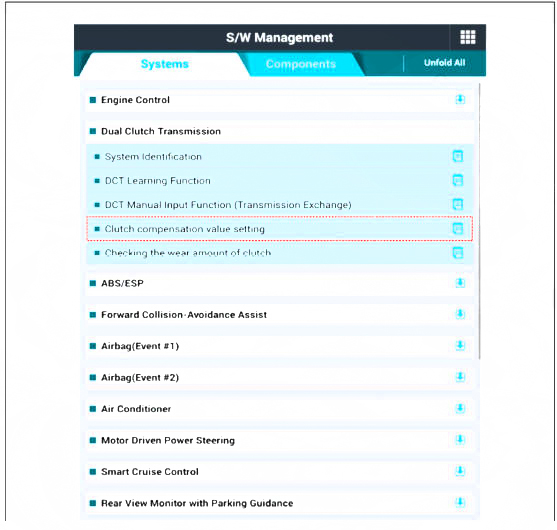
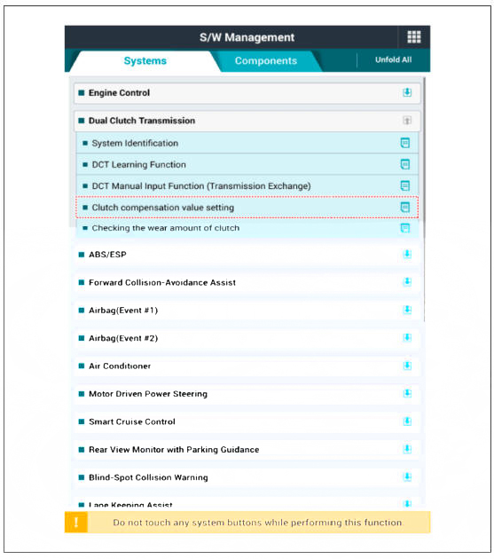
- Prior to replacing the TCM, check the TCM clutch compensation value with the diagnostic tool tool.
- Turn ignition switch OFF and disconnect the battery negative (-) terminal.
- Remove the clutch actuator assembly.
(Refer to Dual Clutch Transmission Control System - "Clutch Actuator & TCM Assembly")
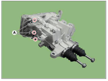
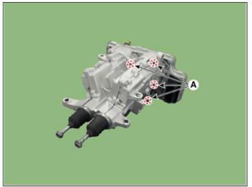
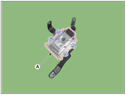
- Loosen the bolts (A) and then removing the TCM (B).
Tightenniug torque: 7.8 - 9.8 N.m (0.8 - 1.0 kgf.m. 5.8 - 7.2 lb-ft)

Installation
- To install, reverse the removal procedure.
WARNING
The existing O-rings (A) must be replaced with a new one. (Do not
reuse it.) 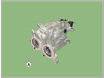
- Perform the clutch compensation value setting procedure using the diagnostic tool after replacing TCM.
WARNING
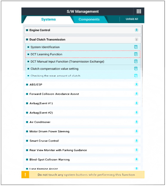
- Before performing the DCT learning procedure using diagnostic tool, perform the learning process after leaving for 5 minutes in the idle state. Because it may be a problem to operation of wear compensation device when entering the DCT learning function at battery low voltage condition.
- When performing the DCT learning function, Perform the DCT learning function twice to ensure accuracy and reliability of the clutch touch point.
- When the ignition is turned off after completing the 2 steps of the DCT learning procedure, the operation of wear compensation device will be performed. It takes up to 6 minutes for the operation of the wear compensation device to be completed, during which time it should not be started engine.
- The engine must be started after at least 6 minutes to ensure that the wear compensation device is fully operated, (keep the engine off for at least 6 minutes)
- If the engine is started while the wear compensation device is operating, sufficient operation of the wear compensation device is not possible, so the excessive operation of the wear compensation device may occur in the next engine starting cycle
- Perform the clutch touch point learning procedure using the diagnostic tool after replacing TCM
Component Location
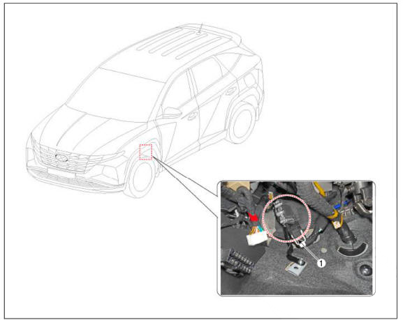
- Shift by wire Control Unit (SCU)
Schematic Diagrams
Removal
- Turn ignition switch OFF and disconnect the negative (-) batteiy cable.
- Disconnect the SBW control unit connector (A).
- Loosen the nut and bolts and then removing the SBW control unit bracket assembly (A).
Tightening torque : 9.8 - 11.8 N.m (1.0 - 1.2 kgf.m, 7.2 - 8.7 lb-ft)
- Loosen the bolts and then removing the SBW control unit (A) from the bracket.
Tightening torque : 9.8 - 11.8 N.m (1.0 - 1.2 kgf.m, 7.2 - 8.7 lb-ft)
Installation
- To install, reverse the removal procedure.
Description
- Components location : DCT (Dual Clutch Transmission)
- Function
The clutch actuator receives signals from the Transmission Control Module (TCM) and controls the clutch.
READ NEXT:
 Clutch actuator assembly - Components
Components
Fork cover
Clutch actuator & TCM assembly
Clutch actuator assembly
O-ring
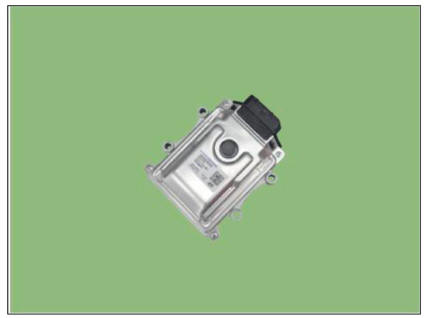
DCT control module (TCM)
Specification
Removal
Turn ignition switch OFF and disconnect the battery negative (-)
terminal.
Remove
Gear actuator assembly
Components
Gear actuator assembly
Specification
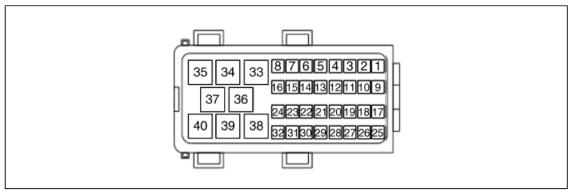
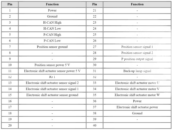
Connector and Terminal Function
Circuit Diagram
Removal
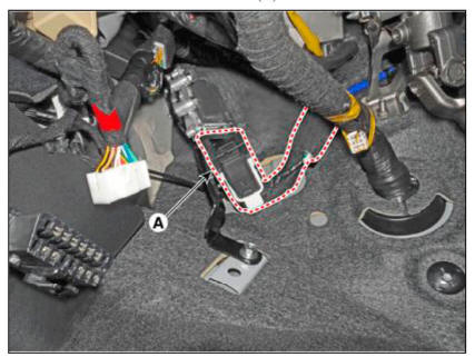
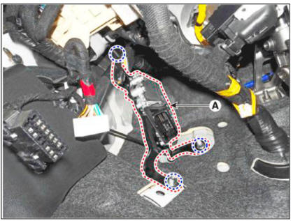
Turn ignition switch OFF and disconnect the negative (-) battery cable.
Remove the air cleaner assembly and ai
Gear actuator assembly- Installation
To install, reverse the removal procedure.
WARNING
Check the details below before installing the gear acmator
assembly.
1)Check that the gear acmator is placed in the "neutral" state.
2)Check the assembled state of the O-ri
SEE MORE:
Lane Keeping Assist Settings
Setting features
Lane Safety
With the engine on, select 'Driver
Assistance → Lane Safety' from the
Settings menu to set whether or not to
use each function.
If 'Assist' is selected, Lane Keeping
Assist will automatically assist th
Clutch touch-point learning
WARNING
Clutch touch-point learning status can be checked through the
cluster lamp.
Prior to learning. "E" lamp turns on. After learning, the
current gear position (N) replaces the "E" lamp and blinks.
Check t
Information
- Home
- Hyundai Tucson - Fourth generation (NX4) - (2020-2023) - Owner's Manual
- Hyundai Tucson - Fourth generation (NX4) - (2020-2023) - Workshop Manual
