Hyundai Tucson: Clutch actuator assembly - Components
Components
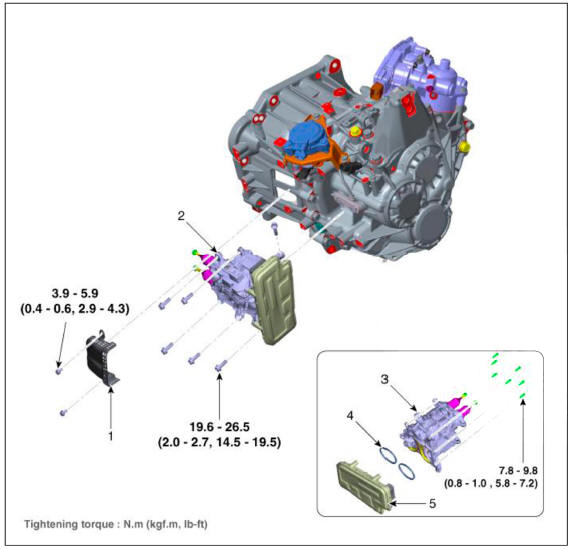
- Fork cover
- Clutch actuator & TCM assembly
- Clutch actuator assembly
- O-ring
- DCT control module (TCM)
Specification
Removal
- Turn ignition switch OFF and disconnect the battery negative (-) terminal.
- Remove the air cleaner assembly and air duct.
(Refer to Engine Mechanical System - "Air cleaner")
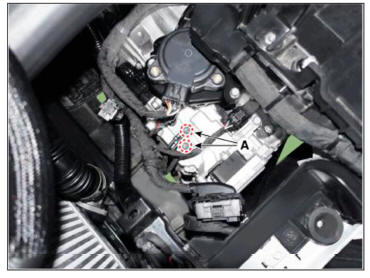
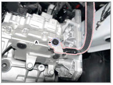
- Disconnect the TCM connector (A).

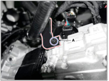
- Loosen the ground mounting bolt (A).
Tightening torque : 9.8- 11.8 N.m (1.0- 1.2 kgf.m. 7.2 - 8.7 lb-ft)
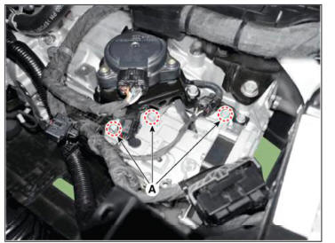
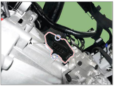
- Loosen the clutch actuator upper mounting bolts (A).
Tightening torque : 19.6 - 26.5 N.m (2.0 - 2.7 kgf.m, 14.5 - 19.5 lb-ft)
- Remove the engine room under cover.
(Refer to Engine Mechanical System - "Eugiue Room Under Cover")
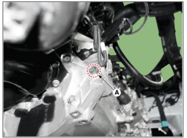
- Loosen the ground mounting bolt (A).
Tightening torque : 9.8- 11.8 N.m (1.0- 1.2 kgf.m. 7.2 - 8.7 lb-ft)
- Loosen the bolt (A) and then removing the wiring bracket.
Tightening torque : 9.8- 11.8 N.m (1.0- 1.2 kgf.m. 7.2 - 8.7 lb-ft)
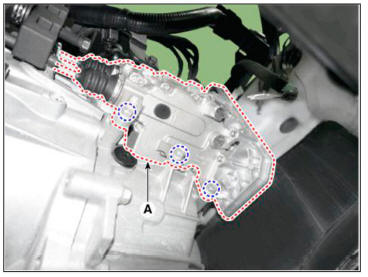
- Loosen the bolts and then removing the fork cover (A).
Tightening torque : 3.9 - 5.9 N.m (0.4 - 0.6 kgf.m. 2.9 - 4.3 lb-ft)
- Loosen the transmission lower mounting bolt (A).
Tightening torque : 42.2 - 53.9 N.m (4.3 - 5.5 kgf.m. 31.1 - 39.8 lb-ft)
- Loosen the starter mounting bolt (A)
Tightening torque : 49.0 - 63.7 N.m (5.0 - 6.5 kgf.m. 36.2 - 47.0 lb-ft)
- Fix the clutch engagement fork after installing special service tool (0K430-Q5100) (A).

- Loosen the clutch acmator lower mounting bolts and then removing the clutch actuator (A).
Tightening torque : 19.6 - 26.5 N.m (2.0 - 2.7 kgf.m. 14.5 - 19.5 lb-ft)
Installation
- To install, reverse the removal procedures.
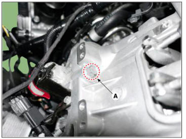
- Check the assembled state of the dowel pins (A) before installing the clutch actuator assembly.

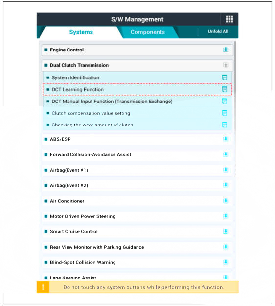
- Perform the clutch touch point learning procedure using the diagnostic tool.
WARNING
- Before performing the DCT learning procedure using diagnostic tool, perform the learning process after leaving for 5 minutes in the idle state. Because it may be a problem to operation of wear compensation device when entering the DCT learning function at batteiy low voltage condition.
- When performing the DCT learning function, Perform the DCT learning function twice to ensure accuracy and reliability of the clutch touch point.
- When the ignition is turned off after completing the 2 steps of the DCT learning procedure, the operation of wear compensation device will be performed. It takes up to 6 minutes for the operation of the wear compensation device to be completed, during which time it should not be started engine.
- The engine must be started after at least 6 minutes to ensure that the wear compensation device is fully operated, (keep the engine off for at least 6 minutes)
- If the engine is started while the wear compensation device is operating, sufficient operation of the wear compensation device is not possible, so the excessive operation of the wear compensation device may occur in the next engine starting cycle
WARNING
- Even if you removed and reinstalled the clutch actuator, be sure to perform the touch point learning.
- If you have replaced the dual clutch assembly or clutch actuator, be sure to perform the touch point learning.
Adjustment
WARNING
- If you replaced the dual clutch assembly or clutch actuator, be
sure to perform wear compensation by referring to the
following table.
- If the rod length is less than 52 mm (2.0472 in.), replace all of the dual clutch assembly, clutch actuator, and engagement bearing.
Initializing the rod length (When only the dual clutch assembly is replaced or Both dual clutch assembly and clutch actuator is replaced)
WARNING
- Be sure to perform it when you have replaced the dual clutch assembly but reuse the clutch acmator.
- Perform the procedure when both the dual clutch assembly and clutch actuator are replaced.
- It is performed to adjust the rod length of an old clutch acmator to that of a new clutch actuator.
- Remove the clutch acmator assembly.
(Refer to C lutch Actuator & TCM Assembly - "Removal")
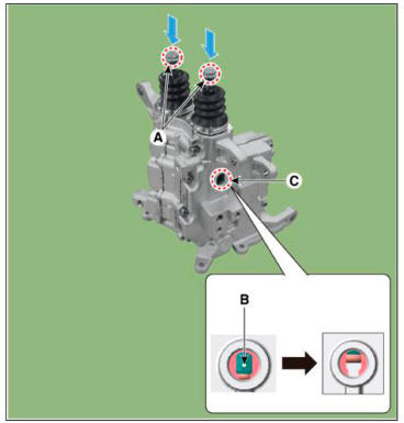
- Remove sealing rubber (A) from old part clutch acmator.

- Slightly pull the rod of the clutch actuator removed from the vehicle and measure length of each rod (C). If the length is shorter than the initialization length, you need to perform initialization.
Rod length (C): Length from the reference plane (A) to the end of the rod (B).
( Iuitializ rod length : 79 - 80 mm (3.1102 - 3.1496 in.)
1)Clutch actuator 1
2)Clutch actuator 2

- Press the end part of rod (A) and release the pressing force when you see the nut bump (B).
WARNING
- Light inside of the hole (C) and check the nut bump (B) inside of it.
- Repeat the operation if the nut bump (B) does not come down to the assembly hole position.
- The nut bump (B) can be moved up a little by sealing boot if the pressing force is released.
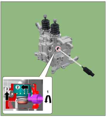
- Insert a special tool (0K430-Q5300) (A) to a sealing rubber hole.
Rotate the SST counter-clockwise and adjust the length of the clutch actuator's rod.
Increasing (+) rod length : Rotate counter-clockwise / once +0.25mm (+0.0098 in.)
Shortening (-) rod length : Rotate clockwise / once -0.25mm (-0.0098 in.)
WARNING
Perform the same procedure for the opposite side rod.
WARNING
- Be aware not to break the clutch actuator caused by break away inner parts when the SST over rotates clockwise.
- If the rod length is not initialized to 79 - 80 mm (3.1102 - 3.1496 in.) during initialization of wear compensation. DCT shift shock may occur or driving may be impossible.
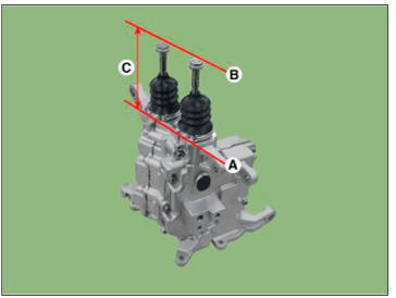
- Slightly pull the rod of the clutch actuator and check whether the "length of the rod which the final adjustment is finished" is same with the "rod's initialized length".
Rod length ( C ) : Length from the reference plane (A) to the end of the rod (B).
( Iuitializ rod length : 79 - 80 mm (3.1102 - 3.1496 in.)
1)Clutch actuator 1
2)Clutch actuator 2
- Install the sealing rubber (A).
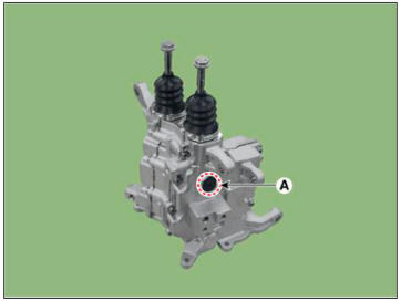
- Remove the clutch acmator assembly from the special tool (0K430-Q5300).
Description
- Components location : DCT (Dual Clutch Transmission)
- Function
The gear actuator comprises the shift motor and select solenoid and the controller.
The gear actuator receives CAN signals from TCM to control the shift motor and the select solenoid for gear shifting.
READ NEXT:
 Gear actuator assembly
Components
Gear actuator assembly
Specification
Connector and Terminal Function
Circuit Diagram
Removal
Turn ignition switch OFF and disconnect the negative (-) battery cable.
Remove the air cleaner assembly and ai
Gear actuator assembly- Installation
To install, reverse the removal procedure.
WARNING
Check the details below before installing the gear acmator
assembly.
1)Check that the gear acmator is placed in the "neutral" state.
2)Check the assembled state of the O-ri
Input shaft speed sensor
Components
Input shaft speed sensor 1 (Odd)
Input shaft speed sensor 2 (Even)
Specification
Circuit Diagram
Removal
Turn ignition switch OFF and disconnect the negative (-) batteiy cable.
Remove the air cleaner assembly a
SEE MORE:
Electrical Circuit Inspection Procedure
Check Open Circuit
Procedures for Open Circuit
Continuity Check
Voltage Check
If an open circuit occurs (as seen in FIG. 1), it can be found by
performing Step 2 (Continuity Check Method) or Step 3
(Voltage Check Method) as sho
Accelerator Position Sensor (APS)
Description
Accelerator Position Sensor (APS) is installed on the accelerator pedal
module and detects the rotation
angle of the accelerator pedal. The APS is one of the most important sensors in
engine control system,
so it consists of the tw
Information
- Home
- Hyundai Tucson - Fourth generation (NX4) - (2020-2023) - Owner's Manual
- Hyundai Tucson - Fourth generation (NX4) - (2020-2023) - Workshop Manual
