Hyundai Tucson: Input shaft speed sensor
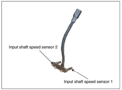
Components
- Input shaft speed sensor 1 (Odd)
- Input shaft speed sensor 2 (Even)
Specification
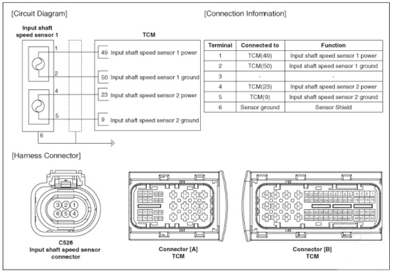
Circuit Diagram
Removal
- Turn ignition switch OFF and disconnect the negative (-) batteiy cable.
- Remove the air cleaner assembly and air duct.
(Refer to Engine Mechanical System - "Air cleaner")
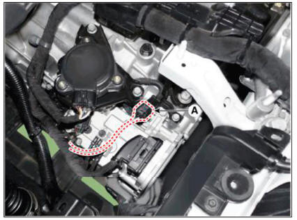
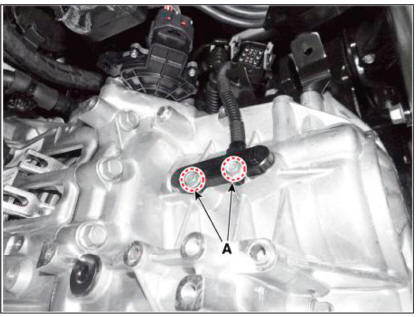
- Disconnect the input speed sensor connector (A).
- Remove the clutch actuator assembly.
(Refer to Dual Clutch Transmission Control System - "Clutch Actuator & TCM Assembly")
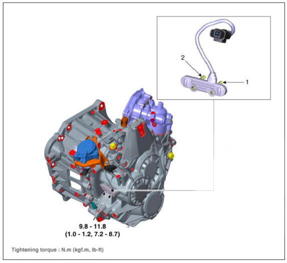
- Remove the input shaft speed sensor after removing the bolts (A).
Tightening torque : 9.8 - 11.8 N.m (1.0 - 1.2 kgf.m, 7.2 - 8.7 lb-ft)
Installation
- To install, reverse the removal procedure.
WARNING
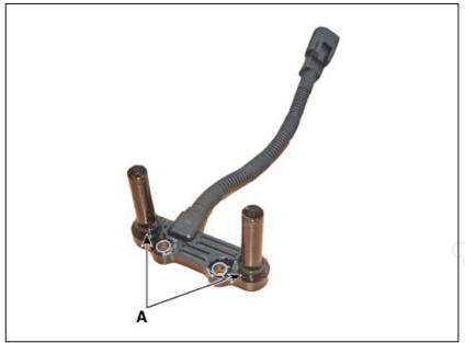
Before installing the input speed sensor,check the assembled state
of the O-rings (A) and should
apply gear oil to the surface of O- rings.
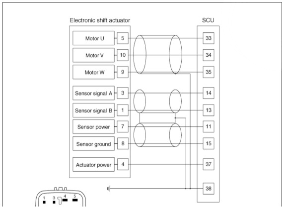
Description
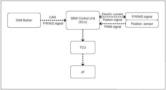
Controls the 4 position of P( Parking), R. N. D using the rotation of the motor of according to the electric signal when the shift button is operated.
Specification
Connector and Terminal Function
Circuit Diagram
READ NEXT:
 Input shaft speed sensor- Removal
Removal
Turn ignition switch OFF and disconnect the negative (-) batteiy cable.
Remove the air cleaner assembly and air duct.
(Refer to Engine Mechanical System - "Air cleaner")
Disconnect the electronic shift actuator connecto
Input shaft speed sensor- Installation
Installation
Check that the shaft is in the "N" position.
Install the position sensor (A) and then lightly tighten the bolts.
Install the position sensor "N" fixing SST(No.:09430-2Cl 10).
Tighten position
Clutch fork and clutch bearing
Components
Clutch housing
Engagement bearing 2 (Even)
Egnagement bearing 1 (Odd)
Engagement bearing sleeve
Clutch engagement fork
Removal
Remove the dual clutch transmission from the vehicle
(Refer to Dual Clutch Transmissio
SEE MORE:
Filling check
WARNING
The procedure below shows about residual air check and removing
it if necessary by using the diagnostic tool after refilling
the IMT system with clutch fluid.
The "IMT filling check" procedure should be performed after
Trip computer (Type B)
The trip computer is a microcomputercontrolled
driver information system that
displays information related to driving.
Information
Some driving information stored in the
trip computer (for example Average
Vehicle Speed) resets if the battery is
Information
- Home
- Hyundai Tucson - Fourth generation (NX4) - (2020-2023) - Owner's Manual
- Hyundai Tucson - Fourth generation (NX4) - (2020-2023) - Workshop Manual
