Hyundai Tucson: Input shaft speed sensor- Installation
Installation
- Check that the shaft is in the "N" position.
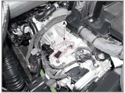
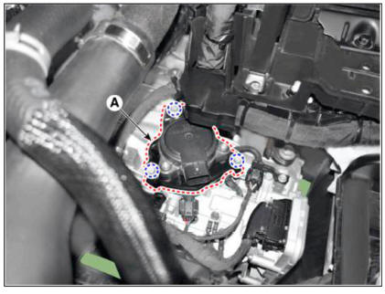
- Install the position sensor (A) and then lightly tighten the bolts.
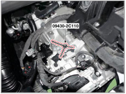
- Install the position sensor "N" fixing SST(No.:09430-2Cl 10).
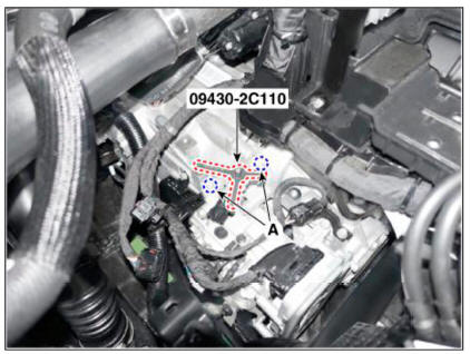
- Tighten position sensor mounting bolts (A) to the specified torque and then remove the position sensor "N" fixing SST(No.:09430-2Cl 10).
Tightening torque : 9.8- 11.8 N.m (1.0 - 1.2 kgf.m, 28.9 - 33.9 lb-ft)
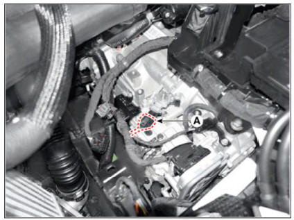
- Connect the position sensor connector (A).
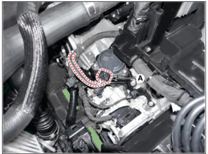
- Install the electronic shift actuator (A).
Tightening torque : 20.6 - 26.5 N.m (2.1 - 2.7 kgf.m, 15.2 - 19.5 lb-ft)
- Connect the electronic shift actuator connector (A).
- Install the air cleaner assembly and air duct.
(Refer to Engine Mechanical System - "Air cleaner")
- Connect the negative (-) batteiy cable.
WARNING
Check that operating surely at each range of the position sensor corresponding to each position of electric shift button.
Description
- Components location : DCT (Dual Clutch Transmission)
- Function
The dual clutch is installed within the transmission.
The dual clutch comprises an odd clutch and an even clutch. The odd clutch transfers and cuts off engine power to the transmission when shifting odd gears.
The even clutch transfers and cuts off engine power to the transmission when shifting even gears.
Removal
- Remove the dual clutch transmission from the vehicle.
(Refer to Dual Clutch Transmission Assembly - "DCT (Dual Clutch Transmission)")
- Remove the retaining ring (A) and then removing the spline hub (B).
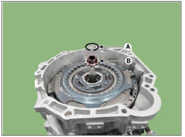
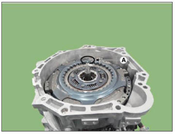
- Remove the snap ring (A).
WARNING
- The snap ring can deform when it removed by forced removal and can't reuse it.
- If it's difficult to remove the snap ring for stuck, release the stuck by using a rubber hammer with a center cylinder of dual clutch installer (09430-2A240) and then remove the snap ring.
- Be careful to damage dual clutch assembly support bearing rubber seal.
WARNING
1)W hen removing is not possible due to snap ring
jamming, place the center cylinder (09430-2A240) and hit it with a
rubber hammer. When it looses, remove it.
2)In case of the dual clutch reuse, make sure not to damage the dual
clutch support bearing rubber seal (A) when
removing the snap ring. 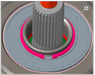
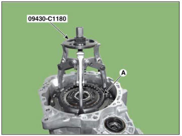
- Remove the dual clutch assembly (A).
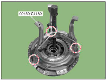
1)Attach the special tool (09430-C1180) to the dual clutch assembly and remove it with a wrench or a spanner.
2)Use a special tool (09430-C 1180) to detach the dual clutch from the transmission housing.
*When detaching the dual clutch from the transmission housing, make sure not to drop the dual clutch.

Installation
WARNING
l)Remove the dust and foreign matters from the input shaft spline (A) and shaft (B).
* Do not use steel soles and sandpapers. WD40 and anti-corrosive
lubricant. (It could cause a corrosion of the rubber or
oil seals.) 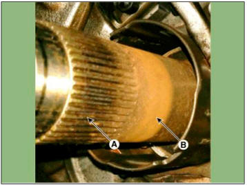
2)Check the grease on the input shaft spline part (A). If there is no grease, apply it to the 10mm point from the each end of the spline.
* Grease overspraying may result excessive scattering and this may cause the clutch to slip.
Specified grease : Extreme pressure grease for vehicle
Quantity : 0.15 - 0.25g 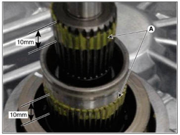
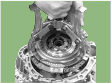
- Fix the special tool (09430-C1180) to the dual clutch assembly at three places at 120-degree intervals, then move to the top of the housing.
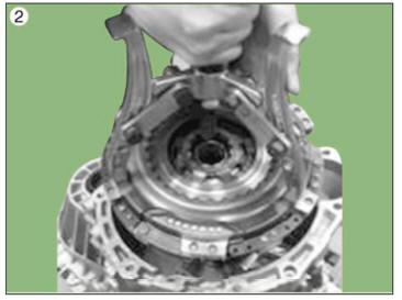
- Assemble the dual clutch to the input shaft 2 temporarily.
WARNING
Dual clutch temporary assembly condition
1)In the input shaft 2. the center bearing inner ring should be properly and temporarily inserted.
2)When th clutch is press-fitted in an unstable temporary assembly,
it may cause damage to the clutch.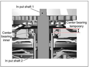
- Install the SST (No.:09430-2A240) on the support bearing within the dual clutch assembly (A).
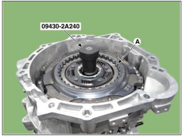
- Install the SST (No. : 09430-2A240) on the clutch housing side.
- Install the dual clutch assembly (A) using the SST (No. : 09430-2A240).

- Install the snap ring (A).
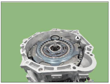
WARNING
After tightening the snap ring (A), see if it can properly rotates
to the right or the left. 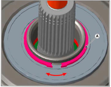
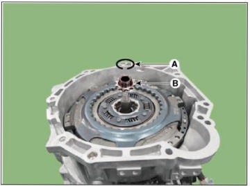
- Install the spline hub (B) and the install the retaining ring (A).
- Install the dual clutch transmission in the vehicle.
(Refer to Dual Clutch Transmission Assembly - "DCT (Dual Clutch Transmission)")
- Perform the work procedures for abrasion compensation reset after installing the new dual clutch assembly.
(Refer to Clutch Actuator & TCM Assembly - "Adjustment")
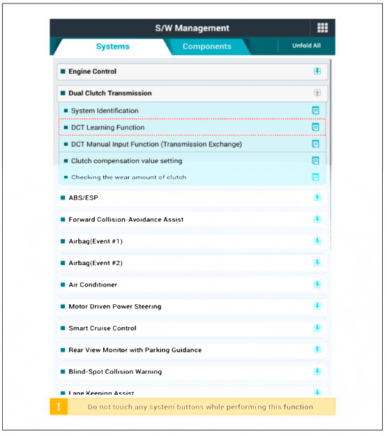
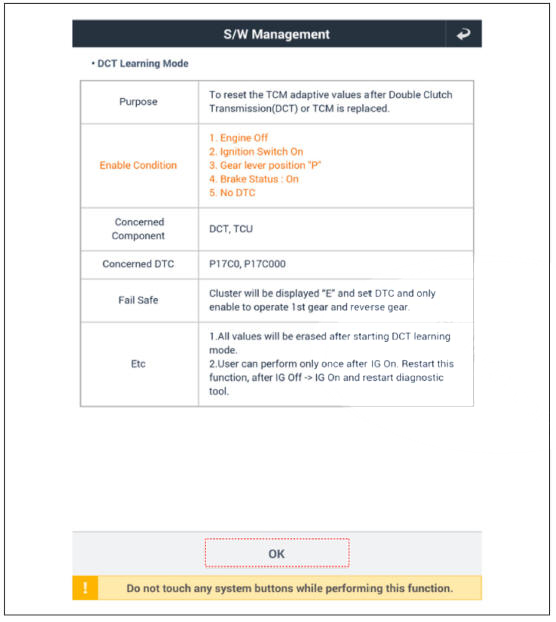
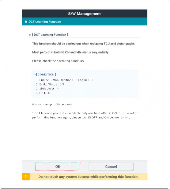
- Perform the clutch touch point learning procedure using the GDS after replacing the dual clutch assembly.
WARNING
- Even if you removed and reinstalled the clutch actuator, be sure to perform the touch point learning.
- If you have replaced the dual clutch assembly or clutch actuator, be sure to perform the touch point learning.
READ NEXT:
 Clutch fork and clutch bearing
Components
Clutch housing
Engagement bearing 2 (Even)
Egnagement bearing 1 (Odd)
Engagement bearing sleeve
Clutch engagement fork
Removal
Remove the dual clutch transmission from the vehicle
(Refer to Dual Clutch Transmissio
SEE MORE:
Curtain Air Bag (CAB)
Components Location
Curtain Air Bag (CAB)
Removal
Disconnect the batteiy negative terminal.
WARNING
After disconnecting the cables, wait at least 3 minutes.
Remove the roof trim.
(Refer to Body - "Roof Trim Assembly"
Rear Wiper Washer - Removal
Disconnect the negative (-) battery terminal.
Loosen the mounting nut and remove the rear wiper arm & blade (A).
WARNING
Take care not to damage the rear glass when removing the rear wiper
arms & blades.
Remove the tail gat
Information
- Home
- Hyundai Tucson - Fourth generation (NX4) - (2020-2023) - Owner's Manual
- Hyundai Tucson - Fourth generation (NX4) - (2020-2023) - Workshop Manual
