Hyundai Tucson: Intake/Exhaust CVVT Timing Mark
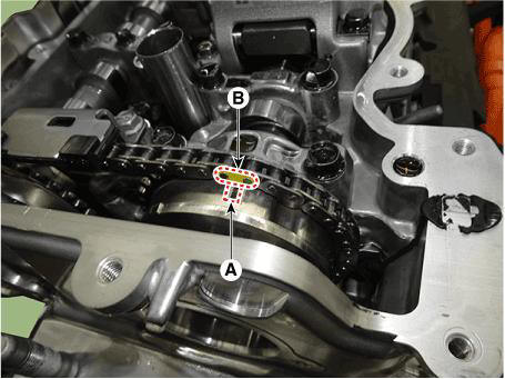
Intake CVVT Timing Mark
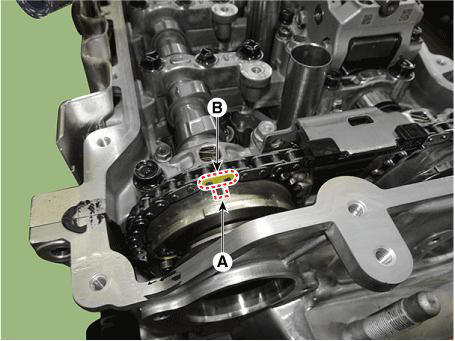
Exhaust CVVT Timing Mark
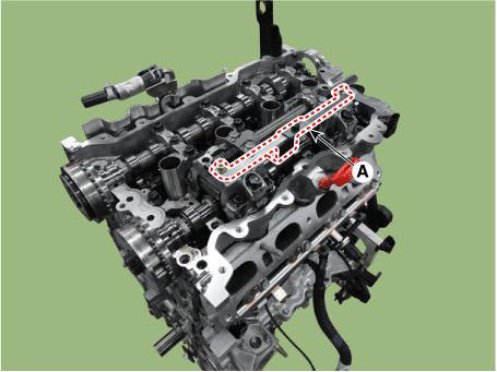
- Install the cam to cam guide (A).
Tightening torque : 9.8 - 11.8 N.m (1.0 - 1.2 kgf.m, 7.2 - 8.7 lb-ft)
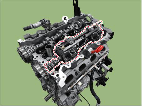
- Install the intake variable force solenoid (VFS) valve (A).
Tightening torque : 9.8 - 11.8 N.m (1.0 - 1.2 kgf.m, 7.2 - 8.7 lb-ft)

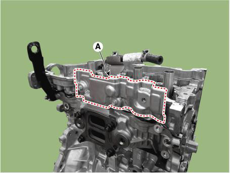
- Install the cylinder head cover.
(Refer to Cylinder Head Assembly - "Cylinder Head Cover")
Removal
WARNING
- Use Fender cover to avoid damaging painted surfaces.
- To avoid damaging the cylinder head, wait until the engine coolant temperature drops below normal temperature before removing it.
- When handling a metal gasket, take care not to fold the gasket or damage the contact surface of the gasket.
- To avoid damage, unplug the wiring connectors carefully while holding the connector portion.
WARNING
- Mark all wiring and hoses to avoid misconnection.
- Turn the crankshaft pulley so that the No. 1 piston is at top dead center.
- Disconnect the negative battery terminal.
Tightening torque :
- Remove the engine cover.
(Refer to Engine and Transaxle Assembly - "Engine Cover")
- Remove the engine room under cover.
(Refer to Engine and Transaxle Assembly - "Engine Room Under Cover")
- Drain the coolant
(Refer to Cooling System - "Coolant")
- Remove the air duct and air cleaner assembly.
(Refer to Intake and Exhaust System - "Air Cleaner")
- Remove the battery and battery tray.
(Refer to Engine Electrical System - "Battery")
- Remove the engine ground cable (A).
Tightening torque : 10.8 - 13.7 N.m (1.1 - 1.4 kgf.m, 8.0 - 10.1 lb-ft)
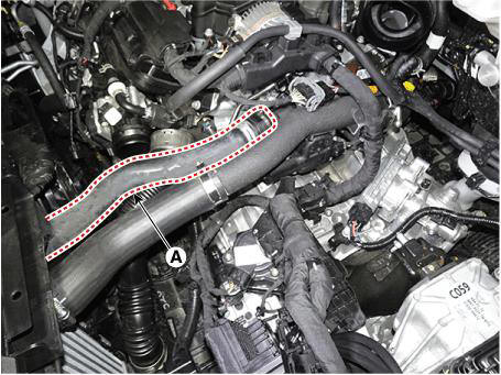
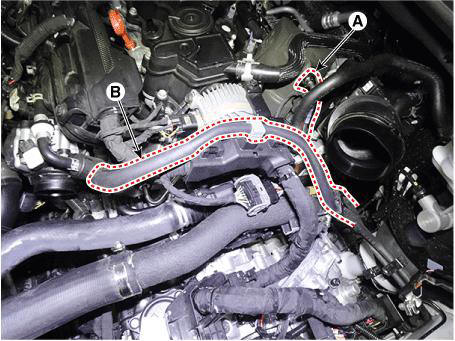
- Disconnect the radiator upper hose (A).
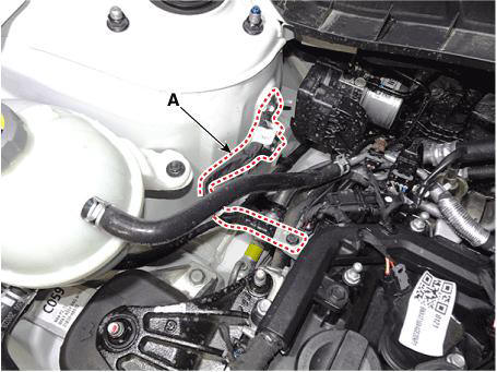
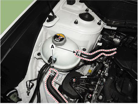
- Disconnect the coolrant reservoir tank coolant hose (A).
- Disconnect the heater hoses (A).
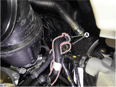
- Disconnect the brake vacuum hose (A).
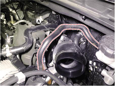
- Disconnect the fuel hose (A) and purge control solenoid valve (PCSV) hose (B).
- Remove the intake manifold.
(Refer to Intake and Exhaust System - "Intake Manifold")
- Remove the delivery pipe.
(Refer to Engine Control / Fuel System - "Delivery Pipe")
- Remove the exhaust manifold.
(Refer to Intake and Exhaust System - "Exhaust Manifold")
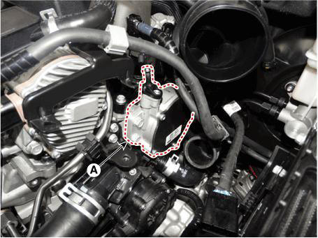
- Remove the vaccum pump (A).
- Remove the integrated thermal management module (ITM).
(Refer to Cooling System - "Integrated Thermal Management Module (ITM)")
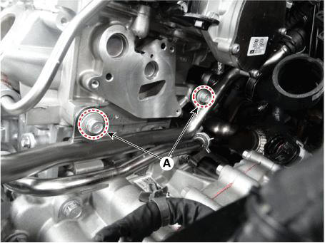
- Remove the heater pipe mounting bolts (A).
- Remove the spark plug.
(Refer to Engine Electrical System - "Spark Plug")
- Remove the timing chain.
(Refer to Timing System - "Timing Chain")
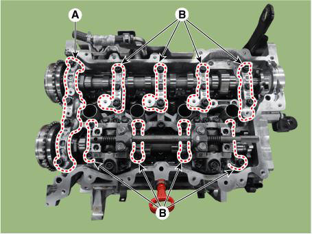
- Remove the camshaft front bearing cap (A) and camshaft bearing caps (B).
- Remove the CVVD assembly (A).
WARNING
- After removing the CVVD unit, make sure that the parts such as lifter, cam, etc are not separated.
- Ensure that the CVVD components are not damaged.
When Using the CVVD fixture
(1) Install the CVVD fixture (A) over the CVVD assembly.
(2) Remove the CVVD assembly (A).

When not using the CVVD fixture
(3) Remove the CVVD assembly (A).
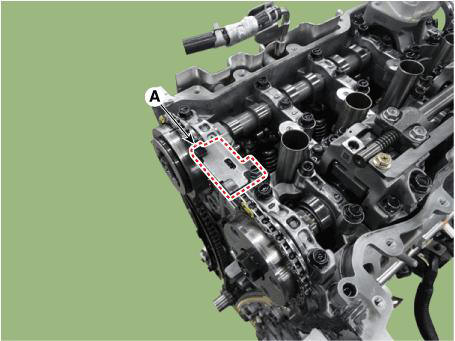
- Remove the exhaust camshaft & CVVT assembly (A).
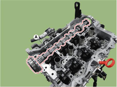
- Remove the cylinder head heat protector (A).
- Remove the cylinder head degasing water hose and pipe (A).
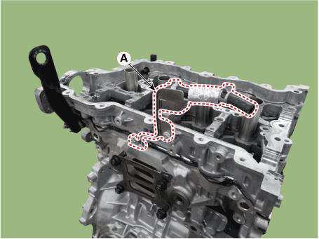
- Remove the cam carrier (A).
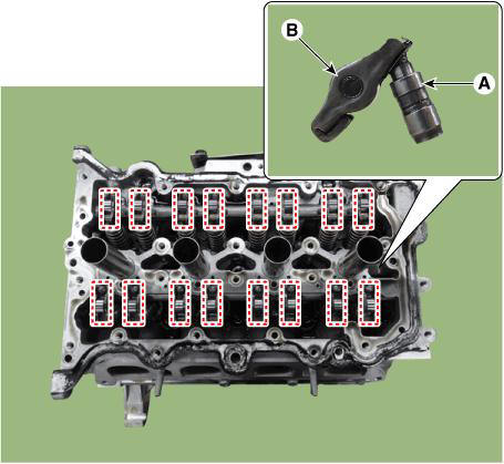
- Remove the hydraulic lash adjuster (HLA) (A) and swing arm (B).
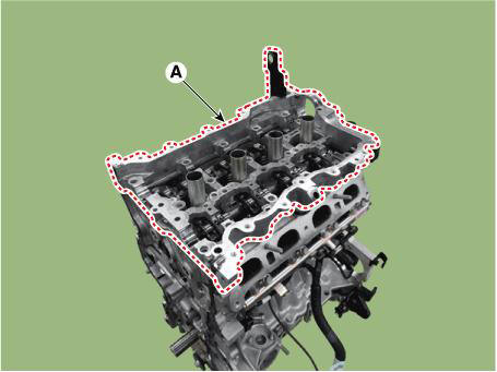
- Remove the cylinder head.
(1) Uniformly loosen and remove the cylinder head bolts, in several passes, in the sequence shown.
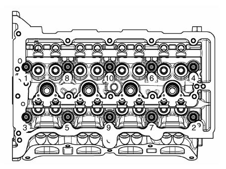
WARNING
- Removing cylinder head bolts in an incorrect order may result in head warpage or crack.
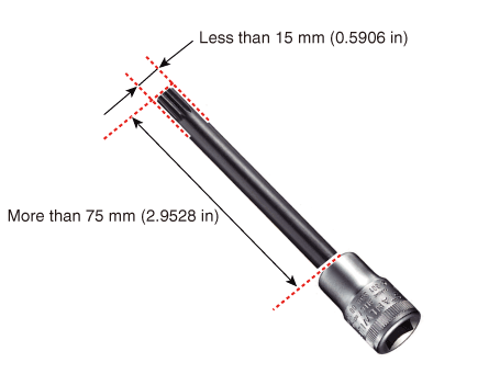
- Use dodecagonal driver socket that has under 15mm(0.5906 in.)
external diameter and longer than
75mm(2.9528 in.) cylinder to not have interference between cylinder head and
dodecagonal driver
socket when the cylinder head bolt removal.
Removing cylinder head bolts in an incorrect order may result in head warpage or crack.
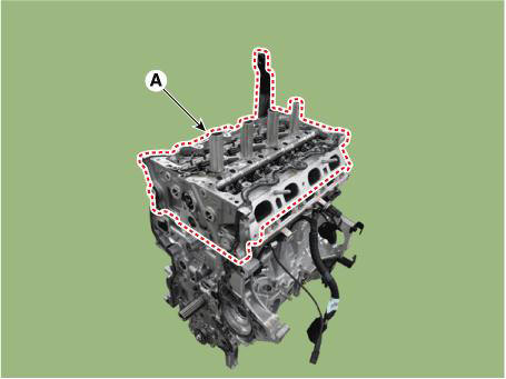
(2) Lift the cylinder head (A) from the cylinder block and put the cylinder head on wooden blocks.
WARNING
Be careful not to damage the contact surfaces of the cylinder head and cylinder block
(3) Remove the cylinder head gasket (A).
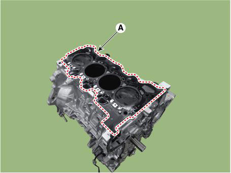
WARNING
Do not reuse the cylinder head gasket
Disassembly
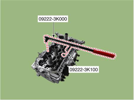
- Remove the valves.
(1) Using the SST (09222-3K000, 09222-3K100), compress the valve spring and remove the valve spring retainer lock (A).
(2) Remove the retainer lock (A) and retainer (B).
(3) Remove the valve spring (C).
(4) Using needle-nose pliers, remove the valve stem seal (D).
(5) Remove the valve (E).
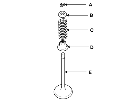
WARNING
Always use new valve stem seals.
Inspection
READ NEXT:
 Cylinder Head
Inspect for flatness.
Using a precision straight edge and feeler gauge, measure the contacting
surface of the cylinder block and the
manifolds for warpage
Flatness of cylinder head gasket surface:
Less than 0.05 mm (0.0020 in.) fo
Cylinder Head - Installation
WARNING
Thoroughly clean all parts to be assembled.
Always use a new cylinder head gasket and manifold gasket.
Always use a new cylinder head bolt and cylinder head bolt
washer.
The cylinder head and exhaust manifold is a metal gasket. T
SEE MORE:
Smart Key System
Component Location (1)
Integrated body control unit (IBU)
Interior antenna 2
Door outside handle
Interior antenna 1
Front antenna
Buzzer
Door antenna
Component Location (2)
Tailgate antenna
Rear bumper antenna
T
Injector - Replacement
The injector combustion seal should be replaced new one to prevent leakage
after removing the injector.
1. Remove the combustion seal (A) with a wire cutter.
WARNING
Grip the sealing ring carefully, pull it to form a small loop
and t
Information
- Home
- Hyundai Tucson - Fourth generation (NX4) - (2020-2023) - Owner's Manual
- Hyundai Tucson - Fourth generation (NX4) - (2020-2023) - Workshop Manual
