Hyundai Tucson: Cylinder Head
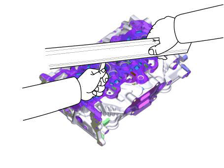
- Inspect for flatness.
Using a precision straight edge and feeler gauge, measure the contacting surface of the cylinder block and the manifolds for warpage
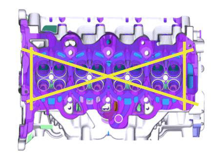
Flatness of cylinder head gasket surface:
Less than 0.05 mm (0.0020 in.) for total area
Less than 0.02 mm (0.0008 in.) for a section of 100 mm (3.9370 in.) X 100 mm (3.9370 in.)
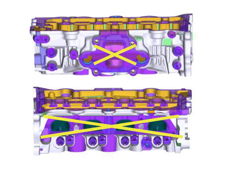
Flatness of manifold mounting surface: Less than 0.10 mm (0.0039 in.)
- Inspect for cracks.
Check the combustion chamber, intake ports, exhaust ports and cylinder block surface for cracks. If cracked, replace the cylinder head.
Valve And Valve Spring
- Inspect valve stems and valve guides.
(1) Using a caliper gauge, measure the inside diameter of the valve guide
Valve guide inner diameter (Intake / Exhaust) : 5.505 - 5.517 mm (0.2167 - 0.2172 in.)
(2) Using a micrometer, measure the outer diameter of valve stem.
Valve stem outer diameter
Intake : 5.465 - 5.480mm (0.2152 - 0.2157in.) Exhaust : 5.458 - 5.470mm (0.2149 - 0.2154in.)
(3) Subtract the valve stem outer diameter measurement from the valve guide inner diameter measurement
Valve stem- to-guide clearance
Intake : 0.025 - 0.052 mm (0.0010 - 0.0020 in.)
Exhaust : 0.035 - 0.059 mm (0.0014 - 0.0023 in.)
If the clearance is greater than specification, replace the valve or the cylinder head.
- Inspect the valves.
(1) Check the valve is ground to the correct valve face angle.
(2) Check that the surface of valve for wear.
If the valve face is worn, replace the valve.
(3) Check the valve head margin thickness.
Valve head thickness (Margin)
Standard
Intake : 0.70 mm (0.0276 in.)
Exhaust : 0.91 mm (0.0358 in.)
If the margin thickness is less than minimum, replace the valve.
(4) Check the length of valve.
Intake : 112.84 mm (4.4425 in.)
Exhaust : 122.83 mm (4.8358 in.)
- Inspect the valve seats.
(1) Check the valve seat for evidence of overheating and improper contact with the valve face. If the valve seat is worn, replace the cylinder head.
(2) Check the valve guide for wear. If the valve guide is worn, replace the cylinder head.
- Inspect the valve springs.
(1) Using a steel square, measure the out-of-square of valve spring.
(2) Using a vernier calipers, measure the free length of valve spring.
Valve spring
Free height
Intake : 52.55 mm (2.0689 in.)
Exhaust : 50.00 mm (1.9685 in.)
Out of square : Less than 1.5º
Reassembly
WARNING
- Thoroughly clean all parts to be assembled.
- Before installing the parts, apply fresh engine oil to all sliding and rotating surface.
- Always use new valve stem seals.
- Install the valves.
(1) After applying engine oil to the valve stem seal, install a new valve stem seal using the special tool (09222- 2B100).
WARNING
- Do not reuse old valve stem oil seals.
- Incorrect installation of the seal could result in oil leakage past the valve guides.
- Do not reassembly ones in the other's places.
WARNING
Intake valve stem seals are different from exhaust ones in type.
(2) Install the spring seats.
(3) Apply engine oil to the entire outer surface of each valve stem and insert the valve inside the valve guide.
(4) Install the valve spring.
(5) Install the retainer.
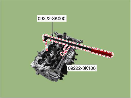
(6) Using the SST (09222-3K000, 09222-3K100), compress the valve spring and install the valve spring retainer lock.
READ NEXT:
 Cylinder Head - Installation
WARNING
Thoroughly clean all parts to be assembled.
Always use a new cylinder head gasket and manifold gasket.
Always use a new cylinder head bolt and cylinder head bolt
washer.
The cylinder head and exhaust manifold is a metal gasket. T
Drive Belt System- Removal and Installation
Components
Crankshaft Damper Pulley
Drive Belt Tensioner
Drive Belt
Removal and
Installation
Fix the drive belt tensioner.
(1) Insert the drive belt tensioner by installing fixing pin (A) after
turning the drive belt tensione
SEE MORE:
Transmission Control Module (TCM) Inspection Procedure - Installation
Installation
To install, reverse the removal procedure.
WARNING
The existing O-rings (A) must be replaced with a new one. (Do not
reuse it.)
Perform the clutch compensation value setting procedure using the
diagnostic tool after rep
Electric WGT Control Actuator- Installation
WARNING
When replacing the Electric WGT Control Actuator, perform the
rod adjustment procedure.
When install the electric WGT control actuator, do not reuse a
C-Ring.
Install in the reverse order of removal.
Adjustment
Rod Adjus
Information
- Home
- Hyundai Tucson - Fourth generation (NX4) - (2020-2023) - Owner's Manual
- Hyundai Tucson - Fourth generation (NX4) - (2020-2023) - Workshop Manual
