Hyundai Tucson: Drive Belt System- Removal and Installation
Hyundai Tucson - Fourth generation (NX4) - (2020-2023) - Workshop Manual / Engine Mechanical System / Drive Belt System / Drive Belt System- Removal and Installation
Components
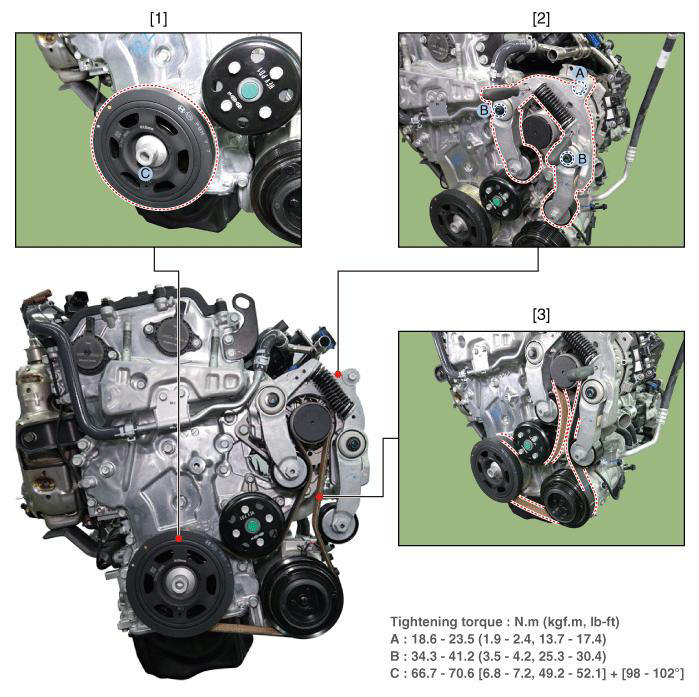
- Crankshaft Damper Pulley
- Drive Belt Tensioner
- Drive Belt
Removal and Installation
- Fix the drive belt tensioner.
(1) Insert the drive belt tensioner by installing fixing pin (A) after turning the drive belt tensioner arm boss (B) to clockwise.
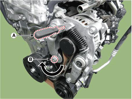
WARNING
- Fix the drive belt tensioner by installing fixing pin after
turning the drive belt tensioner to
clockwise.
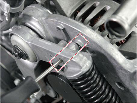
- Use fixing pins that have the same outer diameter as a 6mm(0.2362 in.) hex wrench or a 6mm(0.2362 in.) hex wrench.
(2) Insert the drive belt tensioner by installing fixing pin (A) after turning the drive belt tensioner arm boss (B) to counterclockwise.
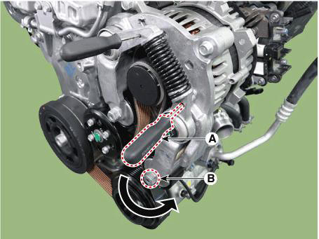
- Remove the drive belt (A).
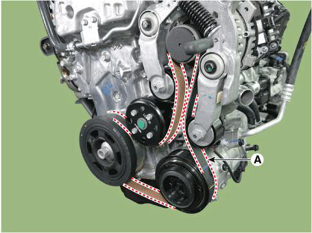
WARNING
When removing the drive belt, remove the drive belt from the water pump pulley.
- Install in the reverse order of removal.
WARNING
When installation of drive belt, make the drive belt as a round hook
shape bigger than
alternater pulley as a picture down below. Then install it with following order
of micro
hybrid starter & generator(MHSG) →
airconditioner compressor → crankshaft
damper pulley
→ water pump.
READ NEXT:
 Drive Belt Inspection
Visually check the belt for excessive wear, frayed cords etc.If any
defect has been found, replace the
drive belt.
WARNING
Cracks on the rib side of a belt are considered acceptable. If the
belt has chunks missing from
the ribs, it sho
Engine And Transaxle Assembly - Removal and Installation
Remove the engine cover (A).
Installation is reverse order of removal
Removal and
Installation
Front Under Cover
Remove the engine room under cover (A).
Tightening torque :
7.8 - 11.8 N.m (0.8 - 1.2 kgf.m, 5.8 - 8.7 lb-ft)
SEE MORE:
Rear wheel speed sensor
Components
2WD
Rear wheel speed sensor
4WD
Rear wheel speed sensor
Rear wheel speed sensor- Removal- 2WD
Removal
2WD
Loosen the wheel nuts slightly.
Raise the vehicle, and make sure it is securely supported.
Remove th
Inside rear view mirror
Component Location
Inside rear view mirror
Replacement
WARNING
When removing with a flat-tip screwdriver or remover, wrap
protective tape around the tools to
prevent damage to components.
Put on gloves to prevent hand injuries.
Information
- Home
- Hyundai Tucson - Fourth generation (NX4) - (2020-2023) - Owner's Manual
- Hyundai Tucson - Fourth generation (NX4) - (2020-2023) - Workshop Manual
