Hyundai Tucson: Cylinder Head - Installation
WARNING
- Thoroughly clean all parts to be assembled.
- Always use a new cylinder head gasket and manifold gasket.
- Always use a new cylinder head bolt and cylinder head bolt washer.
- The cylinder head and exhaust manifold is a metal gasket. Take care not to bend it.
- Turn the crankshaft pulley so that the No. 1 piston is at top dead center.
- Install the cylinder head.
(1) Remove hardening sealant, oil, dust, moisture and harmful foreign materials from the cylinder block and the cylinder head.
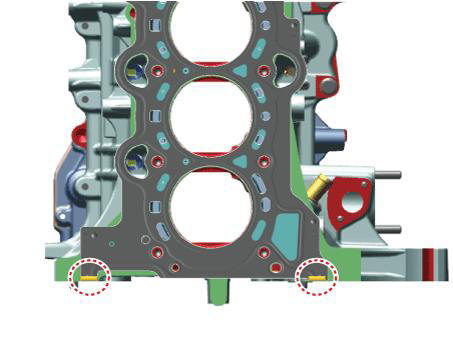
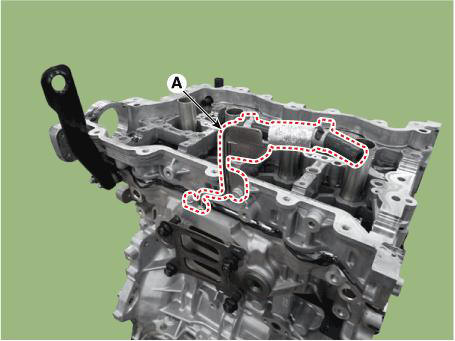
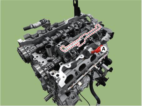
(2) Apply liquid sealant on the upper surface of the cylinder block.
Width : Ø 2.0 - 3.0 mm (0.0787 - 0.1181 in.) Specification : MS721-40AA or above.
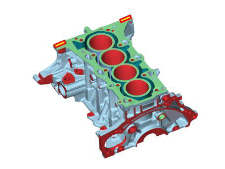
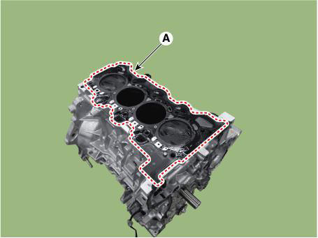
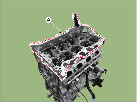
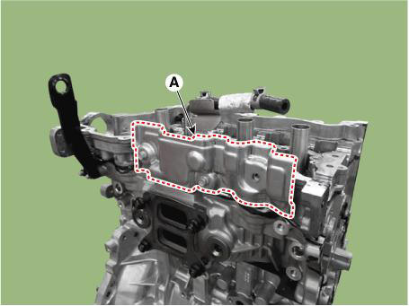
(3) Install the cylinder head gasket (A) to the cylinder block.
WARNING
Be careful not to change the install direction of gasket.
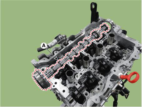
(4) Apply liquid sealant on the upper surface of the cylinder head gasket.
Width : Ø 2.0 - 3.0 mm (0.0787 - 0.1181 in.) Specification : MS721-40AA or above.
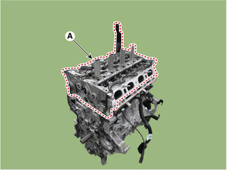
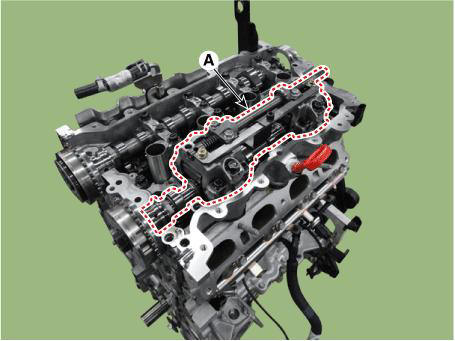
(5) Place the cylinder head (A) carefully not to damage the head gasket.
- Install the new cylinder head bolts.
(1) Do not apply engine oil on the new cylinder head bolts.
(2) Recheck tightening torque 29.4 N*m (3.0 kgf*m, 21.7 lb*ft) of each cylinder head bolt, after installing a new plain washer and a new cylinder head bolt according to the tightening torque 29.4 N*m (3.0 kgf*m, 21.7 lb*ft) in procedure down below.Continuesly tighten with angle tightening torque(90º) following the procedure in picture below after tightening with angle tightening torque(90º) with no stop following the procedure down below.
Tightening torque : 29.4 N.m (3.0 kgf.m, 21.7 lb-ft) + 90º + 90º
WARNING
- Always use a new cylinder head bolt and cylinder head bolt washer.
- Assemble the cylinder head gasket and cylinder head within 5 minutes after applying liquid sealant.
- Remove the extruded sealant within 5 minutes after installing cylinder head bolts.
- When installing the cylinder head bolt, make sure where up/down
direction of the cylinder head bolt
washer part is headed and check if the chamber and round part of the washer
is facing the head of the
cylinder head bolt.
- Use dodecagonal driver socket that has under
15mm(0.5906 in.) external diameter and longer than 75mm
(2.9528 in.) cylinder to not have interference between cylinder head and
dodecagonal driver socket when
the cylinder head bolt installation.
WARNING
Camshaft may rotate unstably, if the shape of the attached side of the carrier has altered by running into a cylinder head and the tool to detach a cylinder head bolt.
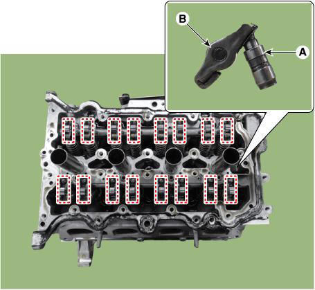
- Install the hydraulic lash adjuster (HLA) (A) and swing arm (B).
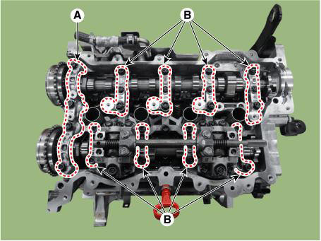
- Install the cam carrier to the cylinder head.
(1) Remove hardening sealant, oil, dust, moisture and harmful foreign materials from the bottom surface of the cam carrier and top surface of the cylinder head.
(2) After applying liquid sealant on the bottom surface of the cam carrier, Continuous bead of sealant should be applied to prevent any path from oil leakage.
Width : Ø 2.5 - 3.5 mm (0.0984 - 0.1378 in.) Specification : MS721-40AA or above.
(3) The dowel pins on the cam carrier and holes on the cylinder head should be used as a reference in order to assemble the cam carrier in exact position.
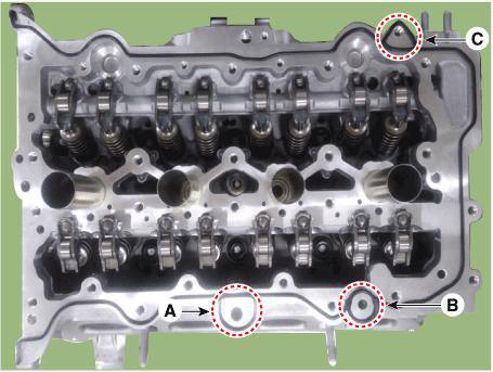
WARNING
When installing the cam carrier to the cylinder head, make sure to
prevent the sealant from entering the
hole of the oil level gauge (A) and the positive crankcase ventilation (PCV) (B)
and high pressure fuel
pump braket mounting hole (C).
(4) Install the cam carrier (A).
Tightening torque :
Bolts (B): 18.6 - 22.6 N.m (1.9 - 2.3 kgf.m, 13.7 - 16.6 lb-ft)
Bolts (C) : 9.8 - 11.8 N.m (1.0 - 1.2 kgf.m, 7.2 - 8.7 lb-ft)
WARNING
- Assemble the cam carrier within 5 minutes after applying sealant.
- Assemble the camshaft bearing cap within 5 minutes after assembling the cam carrier.
- The engine running or pressure test should not be performed within 30 minutes after assembling the cam carrier.
- After installing the cam carrier to the cylinder head, check whether there are sealants in the hole of the oil level gauge and the positive crankcase ventilation (PCV).
- Install the cylinder head degasing water hose and pipe (A).
Tightening torque : 9.8 - 11.8 N.m (1.0 - 1.2 kgf.m, 7.2 - 8.7 lb-ft)
- Install the cylinder head heat protector (A).
Tightening torque : 9.8 - 11.8 N.m (1.0 - 1.2 kgf.m, 7.2 - 8.7 lb-ft)
- Install the exhaust camshaft & CVVT assembly (A).
WARNING
After installing exhaust camshaft, check whether the swing arm is separated or is installed correctly.
- Install the CVVD assembly.
WARNING
- During the installation, there should be no artifical rotation or movement of the guide bracket and control shaft.
- When removing the CVVD fixing jig, be sure to securely tighten the M6 bolts.
- If CVVD fixing jig is available, be sure to work by using it.
When Using the CVVD fixture
- When installing the CVVD assembly mounting bolts (M6), tighten sequence shown.
Tightening torque :
1ST
4.9 - 6.9 N.m (0.5 - 0.7 kgf.m, 3.6 - 5.1 lb-ft)
2nd
9.8 - 11.8 N.m (1.0 - 1.2 kgf.m, 7.2 - 8.7 lb-ft)
- Remove the CVVD fixture (A).
- Provisionally tighten the CVVD assembly mounting bolts (M8) in sequence shown below.
Tightening torque : 9.8 - 11.8 N.m (1.0 - 1.2 kgf.m, 7.2 - 8.7 lb-ft)

- Remove the CVVD assembly mounting bolts (M6) (A).
- Provisionally tighten the CVVD assembly mounting bolts (M6) in sequence shown below.
Tightening torque : 4.9 - 6.9 N.m (0.5 - 0.7 kgf.m, 3.6 - 5.1 lb-ft)
- Tighten the CVVD assembly mounting bolts (M8) in sequence shown below
Tightening torque : 18.6 - 22.6 N.m (1.9 - 2.3 kgf.m, 13.7 - 16.6 lb-ft)

- Tighten the CVVD assembly mounting bolts (M6) in sequence shown below.
Tightening torque : 9.8 - 11.8 N.m (1.0 - 1.2 kgf.m, 7.2 - 8.7 lb-ft)

- Measure the clearance between the control shaft bearing cap and the end of control shaft using a clearance gauge.
Clearance : 0.0 - 0.05 mm (0.0 - 0.002 in.)

When not using the CVVD fixture
- Provisionally tighten the CVVD assembly mounting bolts (M6) in sequence shown below
Tightening torque : 4.9 - 6.9 N.m (0.5 - 0.7 kgf.m, 3.6 - 5.1 lb-ft)

- Provisionally tighten the CVVD assembly mounting bolts (M8) in sequence shown below.
Tightening torque : 9.8 - 11.8 N.m (1.0 - 1.2 kgf.m, 7.2 - 8.7 lb-ft)

- Tighten the CVVD assembly mounting bolts (M8) in sequence shown below.
Tightening torque : 18.6 - 22.6 N.m (1.9 - 2.3 kgf.m, 13.7 - 16.6 lb-ft)
- Tighten the CVVD assembly mounting bolts (M6) in sequence shown below.
Tightening torque : 9.8 - 11.8 N.m (1.0 - 1.2 kgf.m, 7.2 - 8.7 lb-ft)

- Release the torque of control shaft bearing cap bolt (A).

- Push the control shaft bearing cap as close as possible in the direction of the arrow.
- Install the control shaft bearing cap mounting bolts (A).
Tightening torque : 9.8 - 11.8 N.m (1.0 - 1.2 kgf.m, 7.2 - 8.7 lb-ft)
- Measure the clearance between the control shaft bearing cap and the end of control shaft using a clearance gauge.
Clearance : 0.0 - 0.05 mm (0.0 - 0.002 in.)
- Install the camshaft front bearing cap (A) and camshaft bearing caps (B).
WARNING
- If there is enough engine oil on the camshaft front bearing cap and camshaft bearing cap installing bolt and bolt hole, tighten to the minimum required tightening torque.
- Apply engine oil the upper part of the intake / exhaust camshaft journal, then install the camshaft front bearing cap and camshaft bearing cap. The amount of application should be enough to flow down both the front and back sides when it is applied to the center
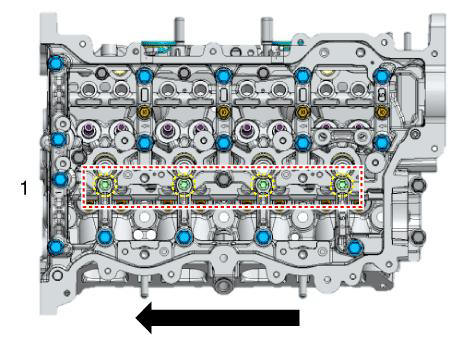
1) Install the camshaft front bearing cap and camshaft bearing cap installing bolt with direction from back of engine to the front of engine according to the procedure at down below.
Tightening torque : 4.9 - 6.9 N.m (0.5 - 0.7 kgf.m, 3.6 - 5.1 lb-ft)

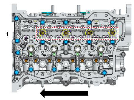
2) Install the camshaft bearing cap installing bolt with direction from back of engine to the front of engine according to the procedure at down below.
Tightening torque : 4.9 - 6.9 N.m (0.5 - 0.7 kgf.m, 3.6 - 5.1 lb-ft)
3) Install the camshaft bearing cap installing bolt with direction from back of engine to the front of engine according to the procedure at down below.
Tightening torque : 4.9 - 6.9 N.m (0.5 - 0.7 kgf.m, 3.6 - 5.1 lb-ft)
- 4) Install the camshaft front bearing cap and camshaft bearing cap installing bolt with direction from back of engine to the front of engine according to the procedure at down below.
Tightening torque : 9.8 - 11.8 N.m (1.0 - 1.2 kgf.m, 7.2 - 8.7 lb-ft)

5) Install the camshaft front bearing cap and camshaft bearing cap installing bolt with direction from back of engine to the front of engine according to the procedure at down below.
Tightening torque : 18.6 - 22.6 N.m (1.9 - 2.3 kgf.m, 13.7 - 16.6 lb-ft)
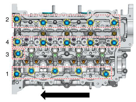
- 6) Install the camshaft bearing cap installing bolt with direction from back of engine to the front of engine according to the procedure at down below.
Tightening torque : 11.8 - 13.7 N.m (1.2 - 1.4 kgf.m, 8.7 - 10.1 lb-ft)

7) Install the camshaft bearing cap installing bolt with direction from back of engine to the front of engine according to the procedure at down below.
Tightening torque : 11.8 - 13.7 N.m (1.2 - 1.4 kgf.m, 8.7 - 10.1 lb-ft)

- Install the other parts in the reverse order of removal.
- Fill with engine coolant.
(Refer to Cooling System - "Coolant")
WARNING
The coolant must be injected according to the integrated thermal management module (ITM) coolant filling method.
- Refill engine with engine oil.
(Refer to Lubrication System - "Engine Oil")
READ NEXT:
 Drive Belt System- Removal and Installation
Components
Crankshaft Damper Pulley
Drive Belt Tensioner
Drive Belt
Removal and
Installation
Fix the drive belt tensioner.
(1) Insert the drive belt tensioner by installing fixing pin (A) after
turning the drive belt tensione
Drive Belt Inspection
Visually check the belt for excessive wear, frayed cords etc.If any
defect has been found, replace the
drive belt.
WARNING
Cracks on the rib side of a belt are considered acceptable. If the
belt has chunks missing from
the ribs, it sho
SEE MORE:
Evaporative Emission Control System- Installation
Install in the reverse order of removal.
Inspection
Check for the following items visually.
Cracks or leakage of the canister
Loose connection, distortion, or damage of the vapor hose/tube
Canister→ Atmosphere
Caniste
Air cleaner
Filter replacement
The air cleaner filter can be cleaned for
inspection using compressed air. Do not
attempt to wash or to rinse it, as water
will damage the filter. If soiled, the air
cleaner filter must be replaced.
Pull up the air
Information
- Home
- Hyundai Tucson - Fourth generation (NX4) - (2020-2023) - Owner's Manual
- Hyundai Tucson - Fourth generation (NX4) - (2020-2023) - Workshop Manual
