Hyundai Tucson: Rear Driveshaft Assembly- Removal
Components
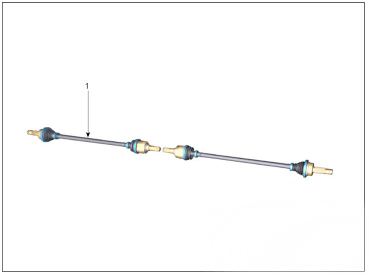
- Rear drive shaft
Removal
WARNING
When lifting a vehicle using a lift, be careful not to damage the lower parts of the vehicle (floor under cover, fuel filter, fuel tank, canister).
(Refer to General Information - "Lift Point")
- Loosen the rear wheel nuts slightly.
Raise the vehicle, and make sure it is securely supported.
- Remove the rear wheel and tire.
(Refer to Suspension System - "Wheel")
- Remove the rear brake caliper.
(Refer to Brake System - "Rear Disc Brake")
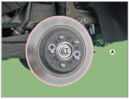
- Remove the rear brake disc (A) after loosening the screw.
Tightening torque : 4.9 - 5.9 N.m (0.5 - 0.6 kgf.m, 3.6 - 4.3 lb-ft)
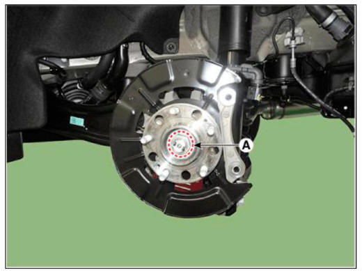
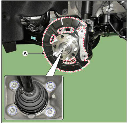
- Loosen the caulking nut (A) from the rear hub.
Tightening torque : 294.2 - 313.8 N.m (30.0 - 32.0 kgf.m, 217.0 - 231.5 lb-ft)
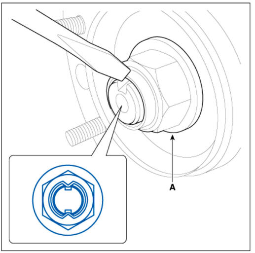
WARNING
- The driveshaft lock nut (A) should be replaced with new ones.
- After installation driveshaft lock nut, stake the lock nut using a chisel and hammer as shown in the illustration below.
Caulking depth : 1.5 mm (0.591 in.)
- Remove the rear hub assembly & dust cover (A) after loosening the mounting bolts.
Tightening torque: 98.0 - 117.6 N.ni (10.0 - 12.0 kgf.m, 72.3 - 86.7 lb-ft)
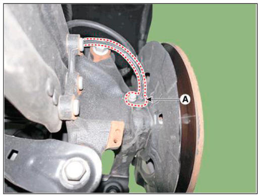
- Remove the rear wheel speed sensor (A) after loosening the mounting bolt.
Tightening torque : 8.8 - 13.7 N.m (0.9 - 1.4 kgf.m. 6.5 - 10.1 lb-ft)
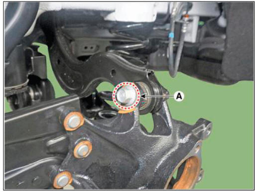
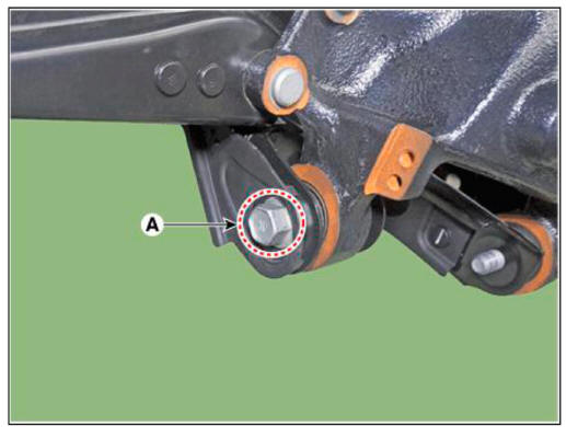
- Remove the rear upper arm from the rear carrier after loosening the mounting bolt and nut (A).
Tightening torque : 137.2- 156.9 N.m (14.0- 16.0 kgf.m, 101.2 - 115.7 lb-ft)
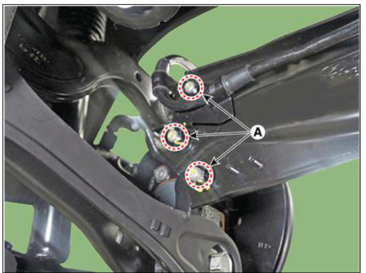
- Remove the trailing arm after loosening the mounting nuts (A).
Tightening torque: 98.0 - 117.6 N.ni (10.0 - 12.0 kgf.m, 72.3 - 86.7 lb-ft)
- Remove the rear assist arm after loosening the mounting bolt and nut (A).
Tightening torque : 156.9 - 176.5 N.ni (16.0 - 18.0 kgf.m, 115.7 - 130.2 lb-ft)
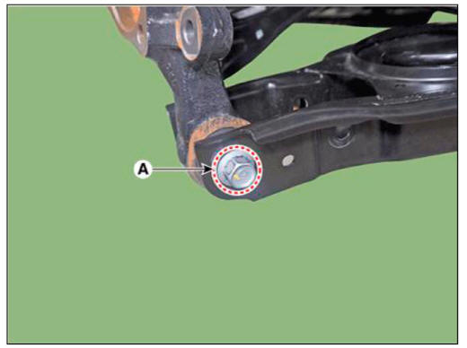
- Remove the rear lower arm after loosening the mounting bolt and nut (A).
Tightening torque : 137.2 - 156.9 N.m (14.0- 16.0 kgf.m, 101.2- 115.7 lb-ft)
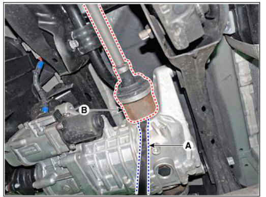
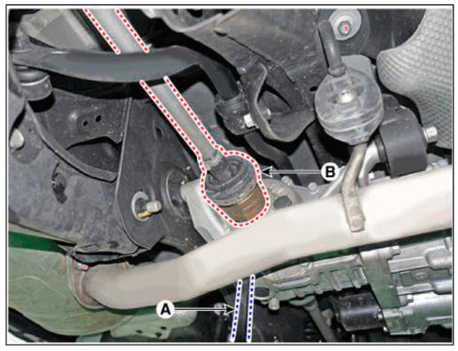
- Remove the rear drive shaft (B) from the differential by using the pry bar (A).
LH
RH
WARNING
- Use a piy bar being careful not to damage the differential and joint.
- Do not insert the pry bar too deep, as this may cause damage to the oil seal.
- Do not pull the driveshaft by excessive force it may cause components inside the joint kit to dislodge resulting in a torn boot or a damaged bearing.
- Plug the hole of the differential case with the oil seal cap to prevent contamination.
- Support the driveshaft properly.
- Replace the retainer ring whenever the driveshaft is removed from the differential case.
READ NEXT:
 Rear Driveshaft Assembly - Disassembly
Disassembly
WARNING
Do not disassemble the BJ assembly.
Special grease must be applied to the driveshaft joint. Do not
substitute with another type of grease.
The boot band should be replaced with a new one.
Remove the TJ boot bands
Propeller Shaft Assembly
Components
Front propeller shaft
Center bearing bracket
Rear propeller shaft
Removal
WARNING
When lifting a vehicle using a lift, be careful not to damage the
lower parts of the vehicle (floor under
cover, fuel filter, fuel tank,
SEE MORE:
Symptom Troubleshooting Guide Chart
Specifications
Fuel Delivery System
Sensors
Manifold Absolute Pressure Sensor (MAPS)
Type : Piezo-Resistive Pressure
Sensor type
Specification
Intake Air Temperature Sensor (IATS)
Type : Termistor type
Specific
Measuring the resistance of the pressure sensor
Turn ignition switch OFF.
Disconnect the pressure sensor connector.
Measure resistance between sensor terminal and terminal.
Check the measured resistance. (Refer to table)
Table 1
Removal
Remove the coupling assembly.
(Refer to
Information
- Home
- Hyundai Tucson - Fourth generation (NX4) - (2020-2023) - Owner's Manual
- Hyundai Tucson - Fourth generation (NX4) - (2020-2023) - Workshop Manual
