Hyundai Tucson: Measuring the resistance of the pressure sensor- Adjustment
Adjustment
Description
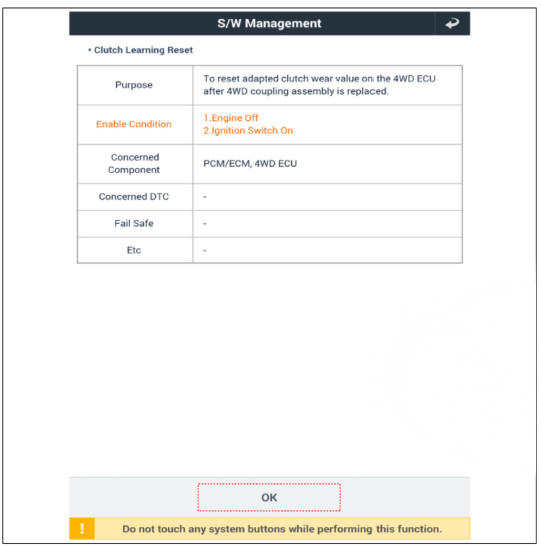
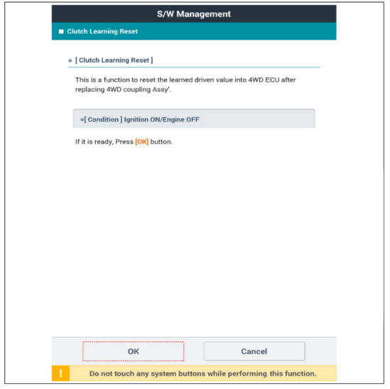
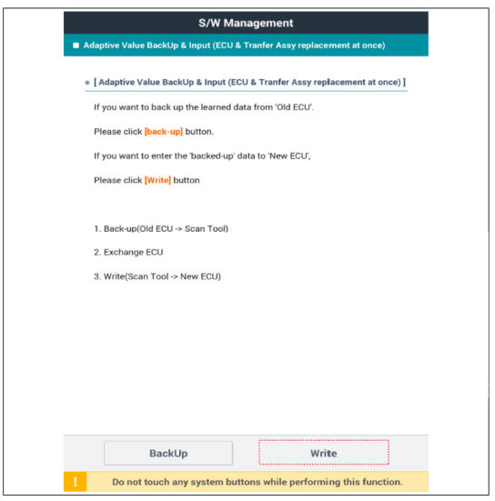
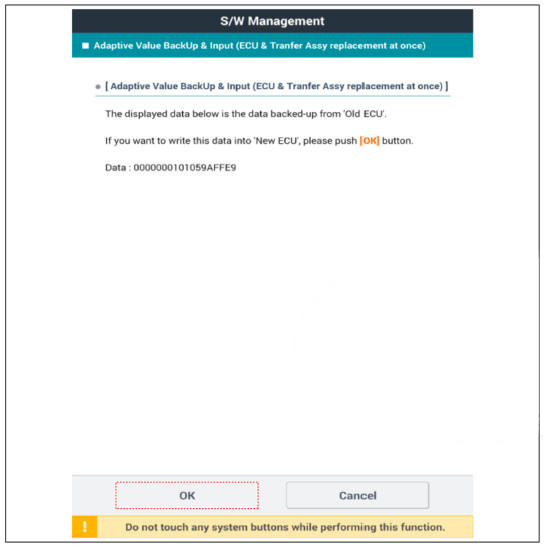
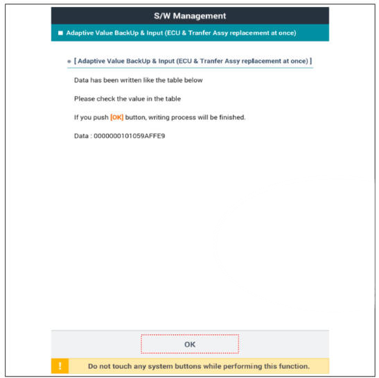
The friction material inside the coupling will degrade over time. Therefore, corresponding compensation values must be referenced and entered after replacing the controller or the coupling.
Compensation Requirement and Procedure
- Simultaneous replacement of 4WD ECU (Controller) and coupling
- Does not require compensation
- Replacement of coupling only
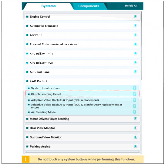
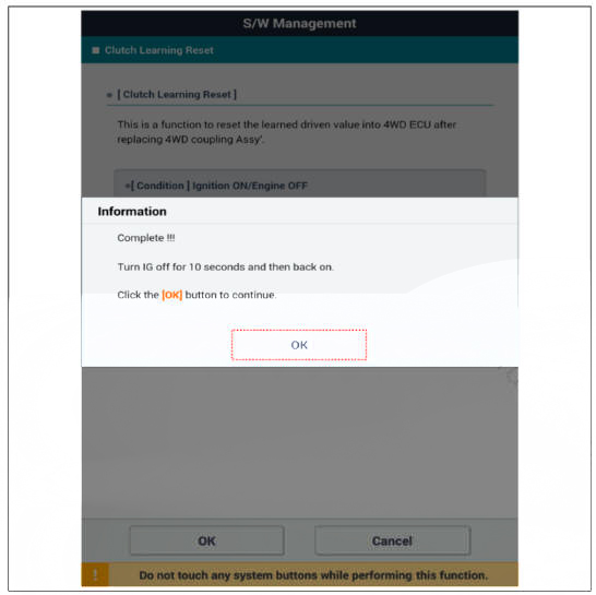
- Reset the 4WD ECU's (Controller) clutch learning.
- Replacement of 4WD ECU (Controller) only
- Before replacement: Check the ECU'S clutch learning.
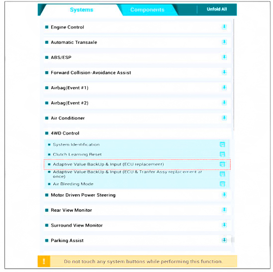
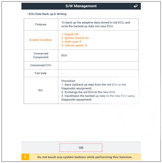
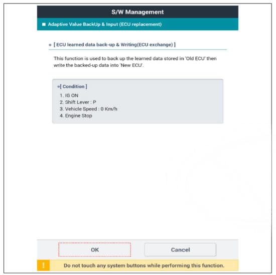


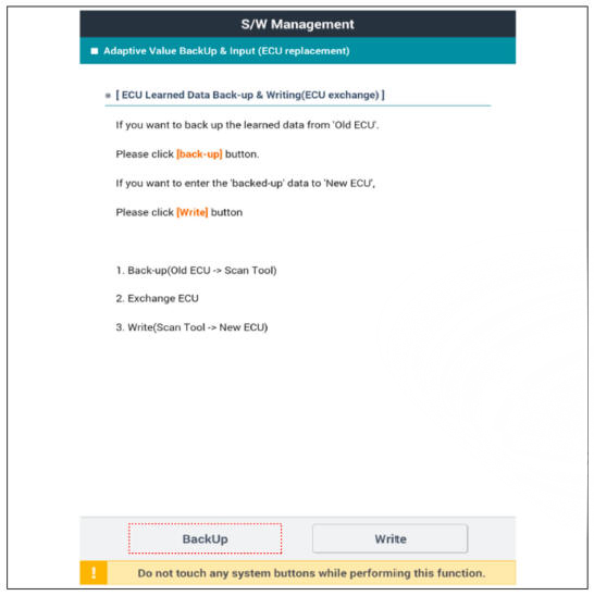
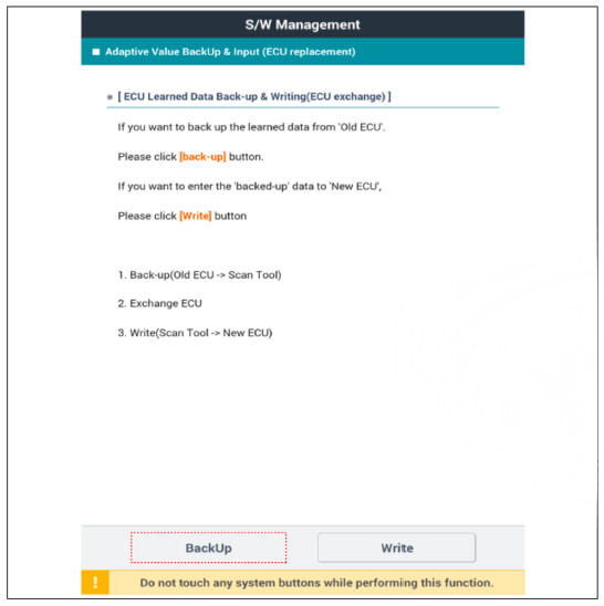

- After replacement: Enter the original ECU'S clutch learning into the replacement ECU.

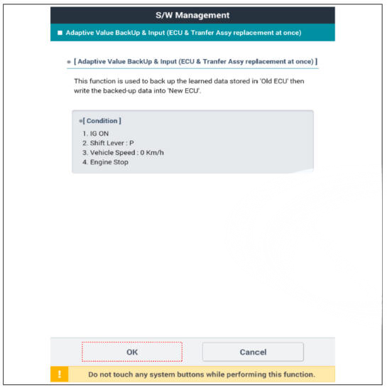
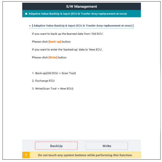
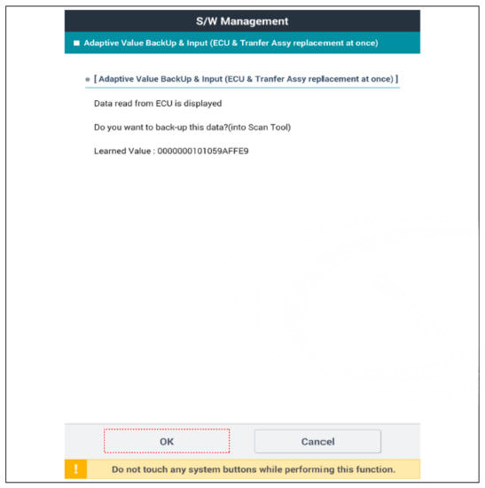
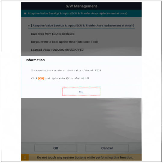
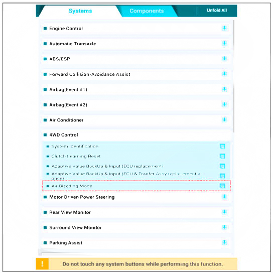
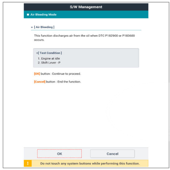
- Perform the following procedure in case of the appearance of failure code (P182900. P183600).

Description
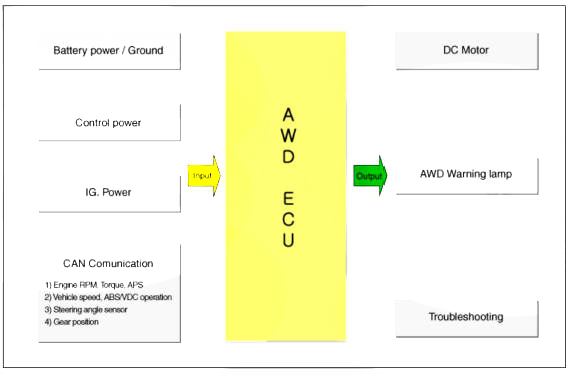
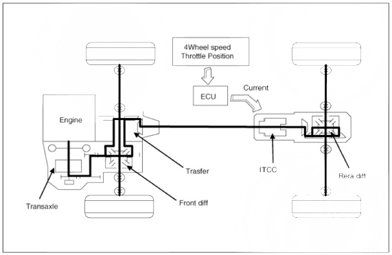
The AWT) ECU distributes the driving force to the front/rear wheel through controlling the multi plate clutch on the AWD transfer case by analyzing the input information, i.e. the wheel speed, accelerator and steering angle depending on the road condition and driving state. The AWD vehicle has different power transmitting conditions depending on the driving/road conditions. The vehicle speed is transmitted through CAN communication from ABS/ESP ECU.
The information from the CAN communication includes the APS which indicates the driver's intention of acceleration, engine torque. ABS/ESP operation signal and gear position. The AWD ECU controls the BLDC' motor, warning lamp and indicating lamp and communicates with the tester equipment. When a vehicle runs at normal speed higher than 60KPH on regular roads, it is controlled under the 2WD conditions. The ECU decides the driving force 011 the front and rear wheel by receiving the signals from all sensors depending on the driving conditions, i.e. abrupt starting, turning and driving 011 the low friction road, and the optimized torque which is proper to the driving condition is transmitted to the front wheel through calculating and controlling the transmitted torque data.
Components Location
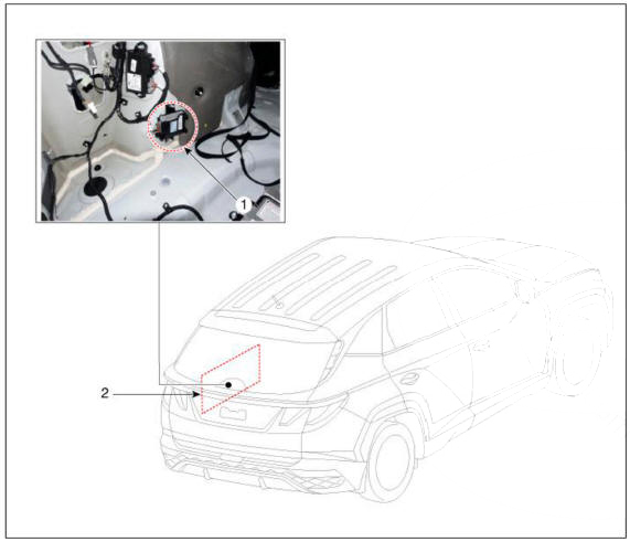
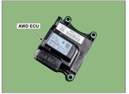
- 4WD ECU
- Luggage side trim Left side
Power Flow Diagram
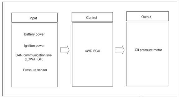
4WD ECU Input&Output Diagram
Circuit Diagram
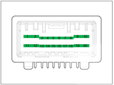
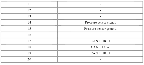
4WD ECU Connector
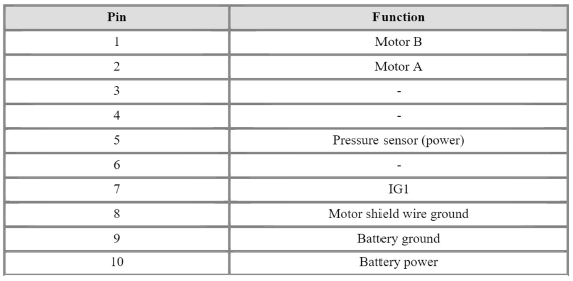
4WD ECU Pin Function
Removal
- Prior to replacing the 4WD ECU, check the 4WD ECU's clutch learing with the diagnostic tool.
(Refer to 4WD Control System - "Repair Procedures")
- Turn OFF ignition switch and the disconnect the negative (-) battery cable.
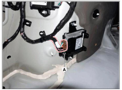
- Remove the luggage side trim. Left side
(Refer to Body (Interior and Exterior) - "Luggage Side Trim")
- Disconnect the 4WD ECU connector (A).
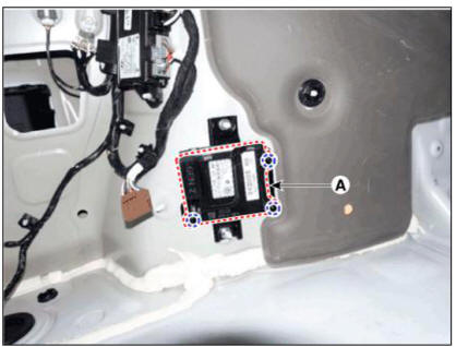
- Loosen the nuts and then removing the 4WD ECU (A).
Tightening torque: 9.8 - 11.8 N.rn (1.0 - 1.2 kgf.m, 7.2 - 8.7 lb.ft)
Installation
- To install, reverse the removal procedures.
- Prior to installing a new ECU, upload the original ECU's clutch learing to the replacement ECU using the diagnostic tool.
(Refer to 4WD Control System - "Repair Procedures")
READ NEXT:
 General Information
Trouble
shooting
Area of
leakage
occuring/ Area/ Type
(1)
Connecting
part/under
part of
transfer case
(2)
Connecting
part of
transmission/ / A
(1) Connecting
part/under
part of
transfer case
(2)
Connecting
part of
transmission
(
Transfer Assembly- Inspection
Inspection
Remove the engine room under cover.
(Refer to Engine Mechanical System - "Engine Room Under Cover")
Loosen the oil filler plug (A).
A Type
B Type
Check the oil level.
WARNING
Oil level must be up to fil
SEE MORE:
LCD display control
The LCD display modes can be changed by using the control buttons.
MODE button for changing modes
MOVE switch for changing items
SELECT/RESET button for setting
or resetting the selected item
Information
When the infotainment system
Wiper blades
Blade inspection
Contamination of either the windshield
or the wiper blades with foreign matter
can reduce the effectiveness of the
windshield wipers.
Common sources of contamination are
insects, tree sap, and hot wax treatments
used by some
Information
- Home
- Hyundai Tucson - Fourth generation (NX4) - (2020-2023) - Owner's Manual
- Hyundai Tucson - Fourth generation (NX4) - (2020-2023) - Workshop Manual
