Hyundai Tucson: Integrated Thermal Management Module (ITM)
Hyundai Tucson - Fourth generation (NX4) - (2020-2023) - Workshop Manual / Engine Mechanical System / Cooling System / Integrated Thermal Management Module (ITM)
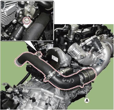
Components
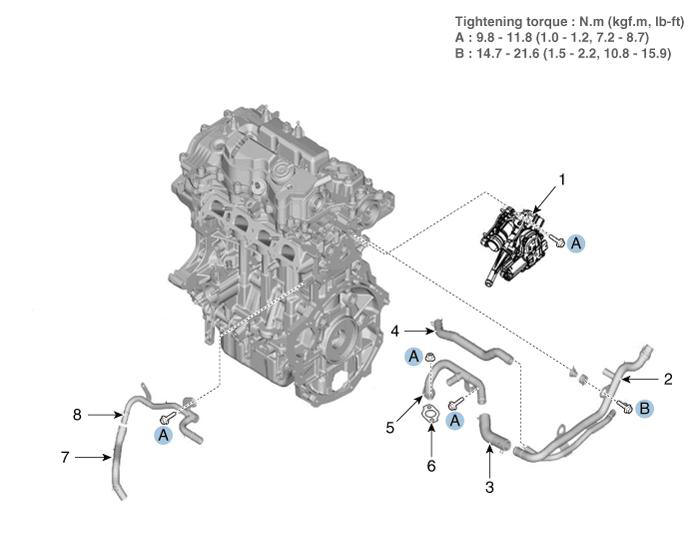
- Integrated thermal management module (ITM)
- Heater pipe
- Heater hose
- Turbo charger coolant hose
- Heater pipe A
- Heater pipe A gasket
- Oil cooler hose A
- Oil cooler pipe
Integrated Thermal Management Module (ITM)
WARNING
- Be careful that static electricity and other voltages are not applied to the integrated thermal management module (ITM).
- Do not bring anything with magnetism, such as a magnet, close to the integrated thermal management module (ITM).
- When disconnecting the integrated thermal management module (ITM) connector, make sure that there is no power to the engine and other components.
- When connecting the integrated thermal management module (ITM) connector, water or oil must be completely removed from the connector and no foreign matters should be entered.
- When replacing the integrated thermal management module (ITM) connector, be sure to use the specified connector.
- Disconnect the battery negative terminal.
- Remove the engine room under cover.
(Refer to Engine and Transaxle Assembly - "Engine Room Under Cover")
- Drain the coolant.
(Refer to Cooling System - "Coolant")
- Remove the air duct and air cleaner assembly.
(Refer to Intake and Exhaust System - "Air Cleaner")
- Remove the battery and battery tray.
(Refer to Engine Electrical System - "Battery")
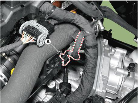
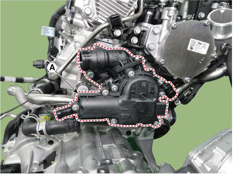
- Disconnect the integrated thermal management module (ITM) connector (A).
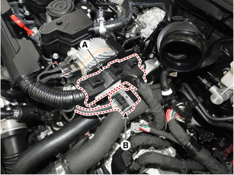
- Separate the main wiring protector (A) from bracket, and then Disconnect the connector (B) from the intercooler inlet pipe.
- Disconnect the intercooler inlet hose (A).
Tightening torque : Clamp bolt : 4.9 - 6.9 N.m (0.5 - 0.7 kgf.m, 3.6 - 5.1 lb-ft)
WARNING
Insert the hose until it reaches the end of stopper.
- Remove the resonator assembly and intercooler pipe (A).
Tightening torque : Mounting bolt : 18.6 - 23.5 N.m (1.9 - 2.4 kgf.m, 13.7 - 17.4 lb-ft)
WARNING
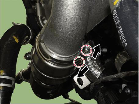
- When disconnecting the resonator assembly, pull the quick
connector clamp in the direction of the
arrow as below.
- When installing the intercooler inlet hose, Match the alignment marks.
- Insert the hose until it reaches the end of stopper.
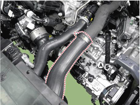
- Disconnect the radiator upper hose (A).
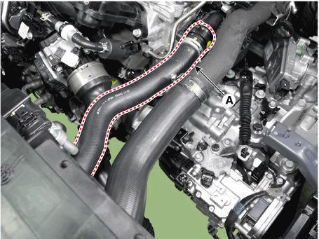
- Disconnect the heater hose (A).
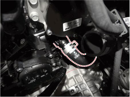
- Disconnect the oil cooler hose (A).

- Remove the integrated thermal management module (ITM) (A).
Tightening torque : 9.8 - 11.8 N.m (1.0 - 1.2 kgf.m, 7.2 - 8.7 lb-ft)
- Install in the reverse order of removal.
- Fill with engine coolant.
(Refer to Cooling System - "Coolant")
WARNING
The coolant must be injected according to the integrated thermal management module (ITM) coolant filling method.
- Start engine and check for leaks.
READ NEXT:
 Heater Pipe
Disconnect the battery negative terminal.
Remove the engine cover.
(Refer to Engine and Transaxle Assembly - "Engine Cover")
Remove the engine room under cover.
(Refer to Engine and Transaxle Assembly - "Engine Room Unde
Oil cooler pipe
Remove the heater pipe
Disconnect the oil cooler hose (A) from the ITM.
Disconnect the oil cooler hose (A) from the oil cooler.
Rmove the oil cooler pipe (A) after loosening the mounting bolts.
Tightening torque :
9.8 - 1
Water Inlet Fitting
Remove the engine room under cover.
(Refer to Engine and Transaxle Assembly - "Engine Room Under Cover")
Drain the coolant.
(Refer to Cooling System - "Coolant")
Disconnect the radiator lower hose (A).
Disconn
SEE MORE:
Fuel requirements
Gasoline engine
Unleaded
Your new vehicle is designed to use only unleaded fuel having an octane
number
((R+M)/2) of 91 (Research Octane Number 95) or higher. (Do not use methanol
blended
fuels)
Your new vehicle is designed to obtain maximum
eCall Parameter Download
eCall Parameter Download is used to change the parameter value of the eCall
law in Europe.
Turn the ignition switch OFF.
Connect the diagnostic tools.
Turn the ignition switch ON without the engine running.
Select the "Car Model"
Information
- Home
- Hyundai Tucson - Fourth generation (NX4) - (2020-2023) - Owner's Manual
- Hyundai Tucson - Fourth generation (NX4) - (2020-2023) - Workshop Manual
