Hyundai Tucson: Initializing Method of the Safety Power Window
- Initializing of Battery Connection
When the battery power is removed for over 5 minutes, safety power window switch need the initializing.
(1) Power window operation before initializing
- Manual-Up/Down function is available
- Auto-Up function is not available (When holding the auto-up/down switch, window is operated as a manual-up/down.)
(2) Initializing method
Close the window in window open position, and holding the switch in window full close position over the 0.2 second.
(If start the closing the window in window full close position, initializing could be failed.)
(3) If initialize the safety power window in jamming status, could occur below conditions.
- Safety function is not available
- Initializing of fail safe mode
(1) If the window moved by compulsion and motor have a problem, power window switch could be entering the fail safe mode for user's safety.
(2) Power window operation in fail mode
- Auto/Manual-Down function is available
- Auto/Manual-Up function is not available
(When auto/manual-up is operated, window is rising 20mm and is stopped the moving.)
Inspection
Front Power Window Motor
- Disconnect the negative (-) battery terminal.
- Remove the front door trim.
(Refer to Body - "Front Door Trim")
- Disconnect the motor connector from the motor.
- Connect the motor terminals directly to battery voltage (12V) and check that the motor operates smoothly. Next, reverse the polarity and check that the motor operates smoothly in the reverse direction. If the operation is abnormal, replace the motor.
Safety Window Motor
- Connect the motor terminals directly to battery voltage (12V) and check that the motor operates smoothly. Next, reverse the polarity and check that the motor operates smoothly in the reverse direction. If the operation is abnormal, replace the motor.
Standard Window Motor
Rear Power Window Motor
- Disconnect the negative (-) battery terminal.
- Remove the rear door trim.
(Refer to Body - "Rear Door Trim")
- Disconnect the motor connector from the motor.
- Connect the motor terminals directly to battery voltage (12V) and check that the motor operates smoothly. Next, reverse the polarity and check that the motor operates smoothly in the reverse direction. If the operation is abnormal, replace the motor.
Safety Window Motor
- Connect the motor terminals directly to battery voltage (12V) and check that the motor operates smoothly. Next, reverse the polarity and check that the motor operates smoothly in the reverse direction. If the operation is abnormal, replace the motor.
Standard Window motor

Driver Power Window Main Switch
Removal
- Disconnect the negative (-) battery terminal.
- Remove the front door trim.
(Refer to Body - "Front Door Trim")
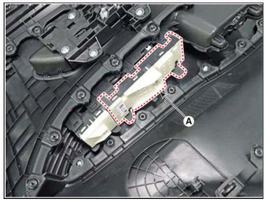
- Remove the power window main switch assembly (A).
Assist Rear Power Window Switch
- Disconnect the negative (-) battery terminal.
- Remove the door trim.
(Refer to Body - "Front Door Trim") (Refer to Body - "Rear Door Trim")
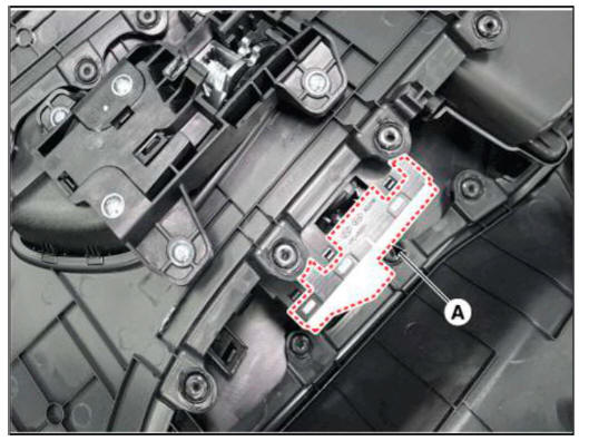
- Remove the assist/rear power window switch assembly (A).
Installation
Power Window Switch
- Install the power window switch assembly.
- Install the front/rear door trim after connecting the connector.
- Connect the negative (-) battery terminal.
Inspection
Diagnosis with diagnostic tool
- In the body electrical system, failure can be quickly diagnosed by using the vehicle diagnostic system (diagnostic tool).
The diagnostic system (diagnostic tool) provides the following information.
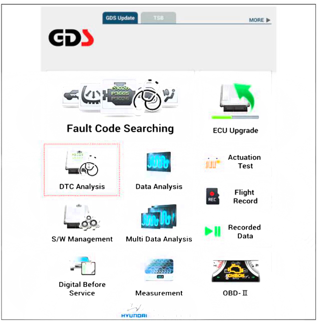
(1) Fault Code Searching : Checking failure and code number (DTC)
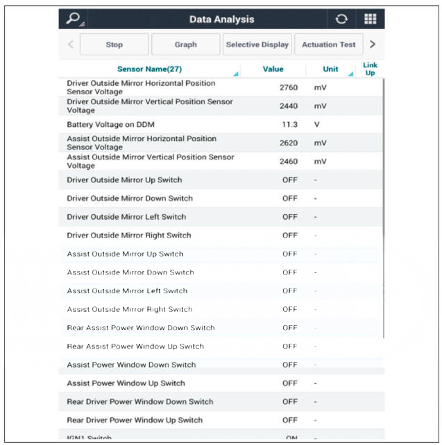
(2) Data Analysis : Checking the system input/output data state
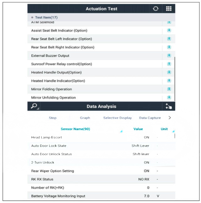
(3) Actuation test: Checking the system operation condition
(4) S/W Management: Controlling other features including system option setting and zero point adjustment
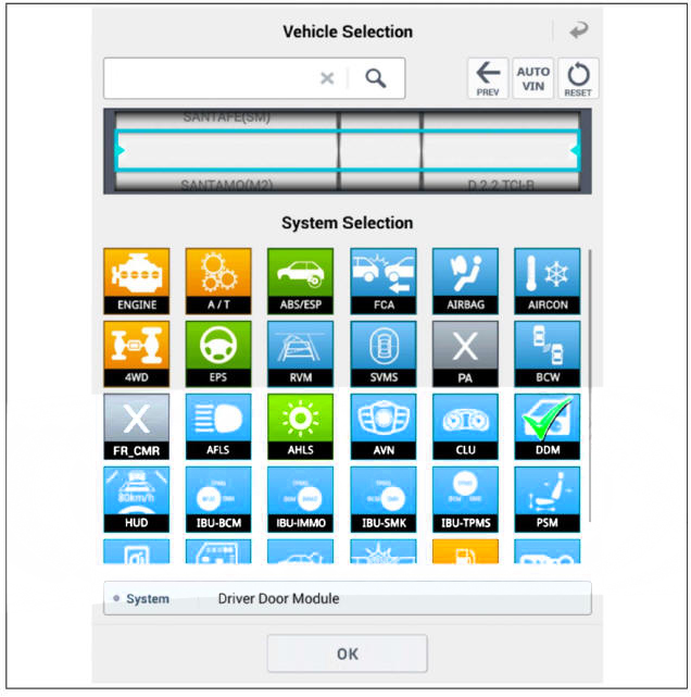
- If diagnose the vehicle by diagnostic tool, select "DTC Analysis" and "Vehicle".
- Select the 'Data Analysis' and 'Car model'.
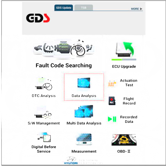
- Select the 'DDM' to search the current state of the input/output data.
- To forcibly actuate the input value of the module to be checked, select option 'Actuation Test'.
READ NEXT:
 Rear Glass Defogger
Inspection
Wrap tin foil around the end of the voltmeter test lead to prevent damaging
the heater line. Apply
finger pressure on the tin foil, moving the tin foil along the grid line to
check for open circuits.
Turn on the defogger swit
Tailgate Position And Direction
Description
Power tailgate is an electro-mechanical system designed to provide power
opening and closing of the tailgate through the
push of a button of a remote key (fob), console switch, inner switch or an
outside handle switch of the tailgat
SEE MORE:
Air cleaner
Filter replacement
The air cleaner filter can be cleaned for
inspection using compressed air. Do not
attempt to wash or to rinse it, as water
will damage the filter. If soiled, the air
cleaner filter must be replaced.
Pull up the air
Keyless Entry And Burglar Alarm
Description
Burglar Alarm State (B/A State)
Remark: On Smart key system, it works the same way with passive lock
Remark: On Smart key system, it works the same way with passive unlock
Remark: On Smart key system, it works
Information
- Home
- Hyundai Tucson - Fourth generation (NX4) - (2020-2023) - Owner's Manual
- Hyundai Tucson - Fourth generation (NX4) - (2020-2023) - Workshop Manual
