Hyundai Tucson: Rear Glass Defogger
Inspection
Wrap tin foil around the end of the voltmeter test lead to prevent damaging the heater line. Apply finger pressure on the tin foil, moving the tin foil along the grid line to check for open circuits.
- Turn on the defogger switch and use a voltmeter to measure the voltage of each heater line at the glass center point. If a voltage of approximately 6V is indicated by the voltmeter, the heater line of the rear window is considered satisfactory.
- If a heater line is burned out between the center point and (+) terminal, the voltmeter will indicate 12 V.
- If a heater line is burned out between the center point and (-) terminal, the voltmeter will indicate OV.
- To check for open circuits, slowly move the test lead in the direction that the open circuit seems to exist. Try to find a point where a voltage is generated or changes to OV. The point where the voltage has changed is the open-circuit point.
- Use an ohmmeter to measure the resistance of each heater line between a terminal and the center of a grid line, and between the same terminal and the center of one adjacent heater line. The section with a broken heater line will have a resistance twice that in other sections. In the affected section, move the test lead to a position where the resistance sharply changes.
Repair Of Broken Heater Line
Prepare the following items :
- Conductive paint.
- Paint thinner.
- Masking tape.
- Silicone remover.
- Using a thin brush :
Wipe the glass adjacent to the broken heater line, clean with silicone remover and attach the masking tape as shown. Shake the conductive paint container well, and apply three coats with a brush at intervals of about 15 minutes apart. Remove the tape and allow sufficient time for drying before applying power. For a better finish, scrape away excess deposits with a knife after the paint has completely dried. (Allow 24 hours).
Inspection
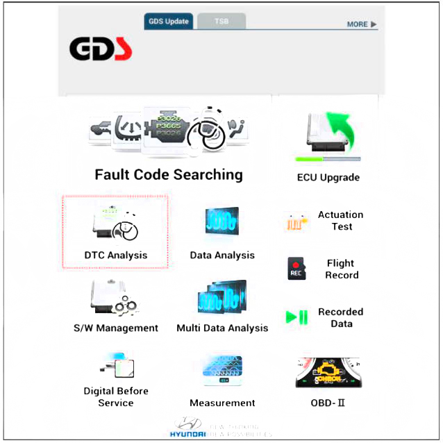
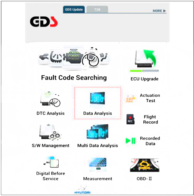
Diagnosis with diagnostic tool
- In the body electrical system, failure can be quickly diagnosed by using the vehicle diagnostic system (diagnostic tool).
The diagnostic system (diagnostic tool) provides the following information.
(1) Fault Code Searching : Checking failure and code number (DTC)
(2) Data Analysis : Checking the system input/output data state
(3) Actuation test: Checking the system operation condition
(4) S/W Management: Controlling other features including system option setting and zero point adjustment
- If diagnose the vehicle by diagnostic tool, select "DTC Analysis" and "Vehicle".
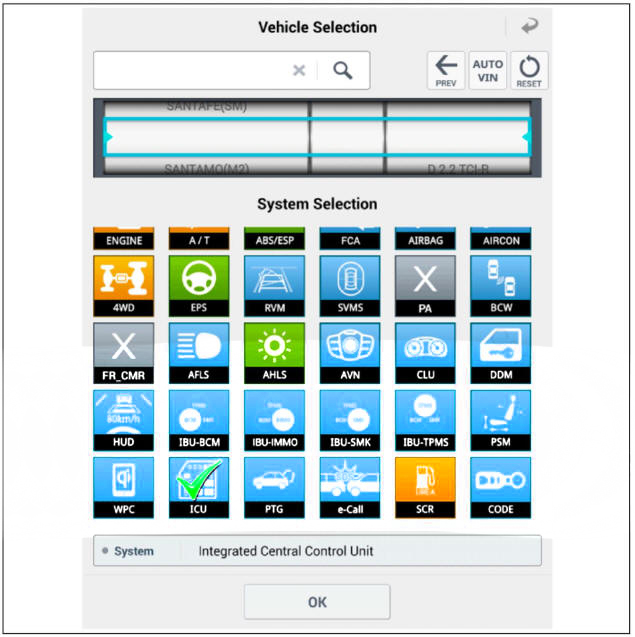
- Select the 'Data Analysis' and 'Car model'.
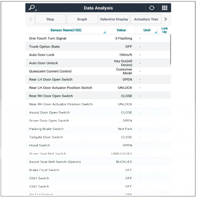
- Select the 'IBU_BCM' to search the current state of the input/output data.
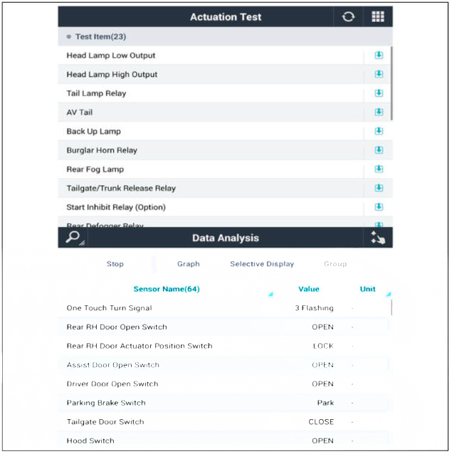
- To forcibly actuate the input value of the module to be checked, select option 'Actuation Test'.
Removal
- Disconnect the negative (-) battery terminal.
- Remove the heater and A/C controll unit.
(Refer to Heating,Veutilatiou, Air Conditioning - "Heater & A/C Control Unit (Manual)") (Refer to Heating, Ventilation, Air conditioning - "Heater & A/C Control Unit (DATC)")
Installation
- Install the heater and A/C control unit.
- Connect the negative (-) battery terminal.
READ NEXT:
 Tailgate Position And Direction
Description
Power tailgate is an electro-mechanical system designed to provide power
opening and closing of the tailgate through the
push of a button of a remote key (fob), console switch, inner switch or an
outside handle switch of the tailgat
Programming the max. T/gate opening (Garage Position)
The customizable Programmed Basic Position is set equal to the Maximum
Basic Position after the Learned Mechanical
End Position is learned.
The customer can change the Programmed Basic Position to any new
position between the Maximum
SEE MORE:
Fuses
A vehicle's electrical system is protected
from electrical overload damage by
fuses.
This vehicle has 5 fuse panels, one
located in the driver's side panel bolster,
the other in the engine compartment.
If any of your vehicle's lights,
Seat Belt Pretensioner
Description
The Seat Belt Pretensioners (BPT) are installed inside Center Pillar (LH & RH).
When a vehicle
crashes with a certain degree of frontal impact, the pretensioner seat belt
helps to reduce the severity of
injury to the front seat
Information
- Home
- Hyundai Tucson - Fourth generation (NX4) - (2020-2023) - Owner's Manual
- Hyundai Tucson - Fourth generation (NX4) - (2020-2023) - Workshop Manual
