Hyundai Tucson: ICU (Integrated Central Control Unit)
Dscription and Operation
ICU (Integrated Central Control Unit) is an integrated model of smart junction block and central gateway.
It performs the function of conventional "Smart junction block" and the function of communication medium of "Central Gateway".

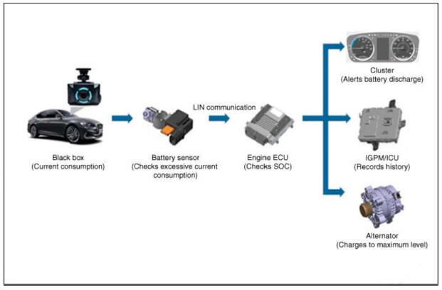
Battery Monitoring System
When the risk of battery discharge is detected due to excessive current consumption from using electrical device such as black box while the engine is OFF.
The system warns the customer of battery discharge through the warning message 011 the cluster.
The battery sensor detects the excessive current consumption of the battery and the Integrated Central control Unit (ICU) records the battery discharge history.
When the battery discharge is detected, the message warning the customer is displayed on the cluster and the battery is charged using the alternator when the engine is driven.
The recorded history can be checked via optional diagnostic tool function: "Check the battery discharge warning history".
Checking the battery discharge warning history
- This function allows checking the history of excessive battery consumption of the parked vehicle.
- It is possible to check the running distance and SOC when the battery consumption was excessive and the current SOC information.
Using diagnostic tool, the "Check the battery discharge warning history" function of ICU is implemented.
- Procedure for coding variants
(1) You should read the specification information for the front view camera that is installed in the vehicle before replacing it with a new front view camera.
(2) Connect the cable of diagnostic tool to the data link connector in driver side crash pad lower panel, and turn on the diagnostic tool.
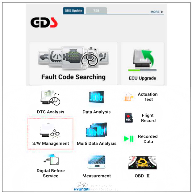
(3) Select the 'S/W Management' and 'Car model'.
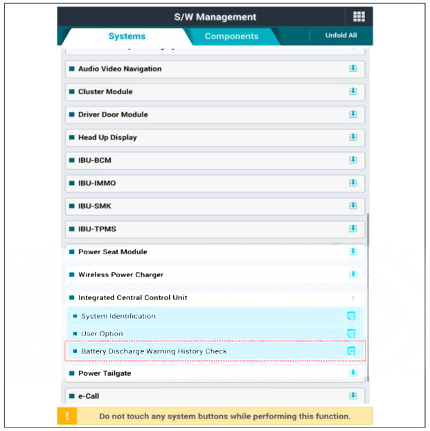
(4) Select the "Integrated Central Control Unit" and "Battery Discharge Warning History Check".
Fuse
Inspection
- Check that the fuse holders are loosely held and that the fuses are securely fixed by the holders.
- Check that each fuse circuit has the exact fuse capacity.
- Check the fuses for any damage.
- If a fuse is to be replaced, be sure to use a new fuse of the same capacity. Always identify the cause of the blown fuse and completely eliminate the problem before installing a new fuse.
Diagnosis with Diagnostic Tool
- In the body electrical system, failure can be quickly diagnosed by using
the vehicle diagnostic system (diagnostic tool).
The diagnostic systemf diagnostic tool) provides the following information.
(1) The diagnostic system(diagnostic tool) provides the following information.
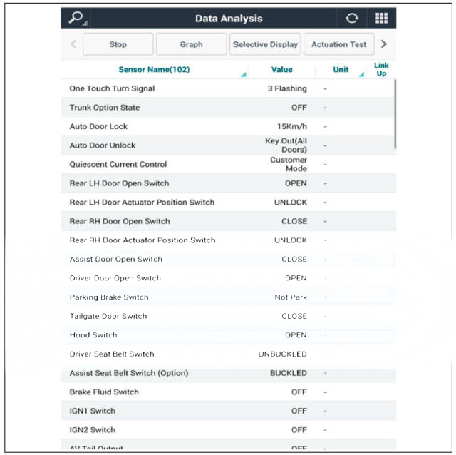
(2) Data Analysis : Checking the system input/output data state
(3) Actuation test: Checking the system operation condition
(4) S/W Management: Controlling other features including system option setting and zero point adjustment
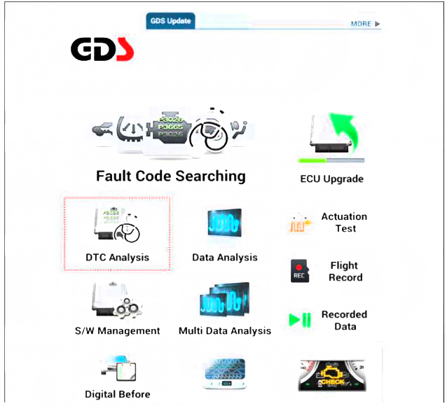
- If diagnose the vehicle by diagnostic tool, select "DTC Analysis" and "Vehicle".

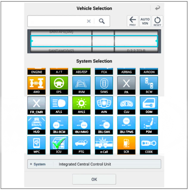
- If check current status, select the "Data Analysis" and "Car model".
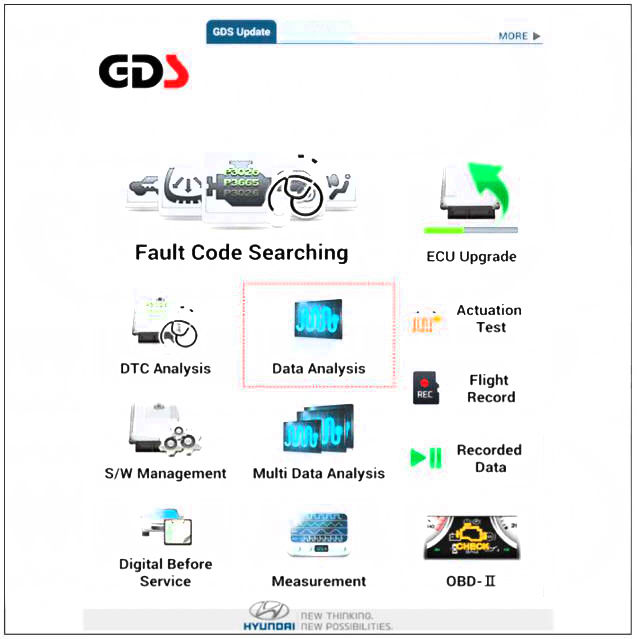
- Select the 'ICU' to search the current state of the input/output data.
Removal
- Disconnect the negative (-) battery terminal.
- Remove the crash pad lower panel.
(Refer to Body - "Crash Pad Lower Panel")
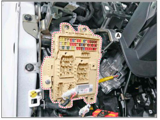
- Disconnect the connectors from the front side of the ICU.
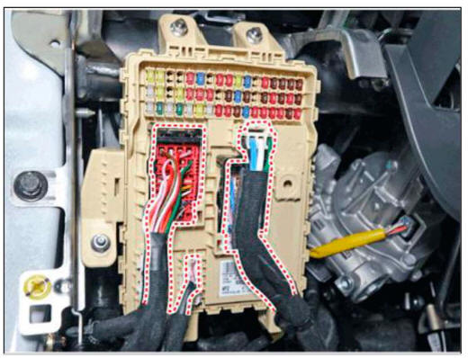
- Remove the ICU (A) after loosening mounting nuts.
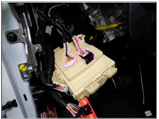
- Disconnect the connectors from the back side of the ICU.
Installation
- Install the ICU.
- Install the crash pad lower panel.
- Connect the negative (-) battery terminal.
READ NEXT:
 Indicators And Gauges
Troubleshooting
Description
Cluster Variant Coding
As we have more options (SCC, VDC, EPB, Cubis, MDPS, TPMS. LDWS, ECS -) in
the car, the
dashboard now has more information to display depending on the chosen options.
For this reason, we
Power Door Locks
Front Door Lock Module Inspection
Inspection
Remove the front door trim.
(Refer to Body - "Front Door Trim")
Disconnect the connectors from the actuator.
Check actuator operation by connecting power and ground according to the
SEE MORE:
Steering wheel - Removal
Components
Lower cover
Haptic motorr
Paddle shift
Steering Wheel
Remote control switch
Switch bezel
Wiring
Drive airbas module (DAB)
Removal
Turn the steering wheel so that the front wheels can face straight ahead.
Turn
Paddle shifter (Manual shift mode)
The paddle shifter is available when
the shift lever/button is in the D (Drive)
position or the manual shift mode.
With the shift lever/button in the D
position
The paddle shifter will operate when the
vehicle speed is more than 6mph.
Pu
Information
- Home
- Hyundai Tucson - Fourth generation (NX4) - (2020-2023) - Owner's Manual
- Hyundai Tucson - Fourth generation (NX4) - (2020-2023) - Workshop Manual
