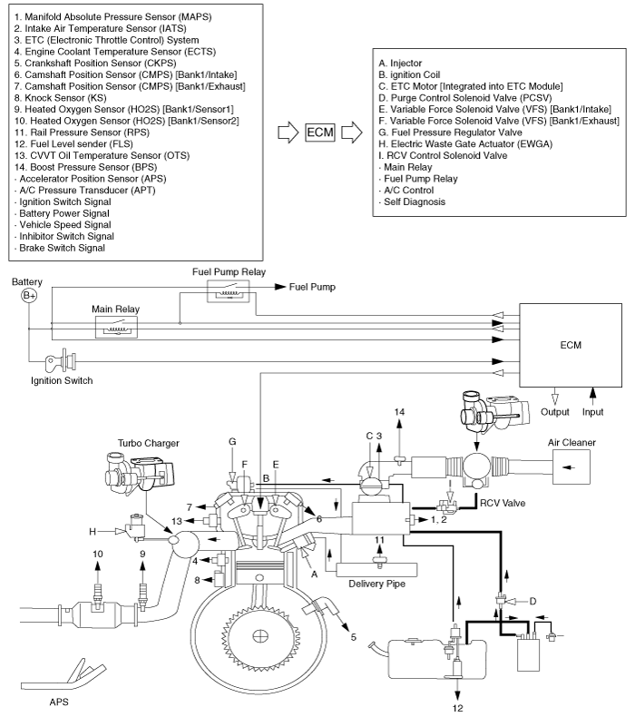
Hyundai Tucson: Schematic Diagrams
Hyundai Tucson - Fourth generation (NX4) - (2020-2023) - Workshop Manual / Emission Control Syste / Schematic Diagrams

- Manifold Absolute Pressure Sensor (MAPS)
- Intake Air Temperature Sensor (IATS)
- ETC (Electronic Throttle Conlrol) System
- Engine Coolant Temperature Sensor (ECTS)
- Crankshaft Position Sensor (CKPS)
- Camshaft Position Sensor (CMPS) Bank1/Intake
- Camshaft Position Sensor (CMPS) Bank/Exhaust
- Knock Sensor (KS)
- Heated Oxygen Sensor (HO2S) Bank1/Sensorl
- Heated Oxygen Sensor (H02S) Bank1/Sensor2
- Rail Pressure Sensor (RPS)
- Fuel Level sender (FLS)
- CVVT Oil Temperature Sensor (OTS)
- Boost Pressure Sensor (BPS)
- Accelerator Pressure Sensor (APS)
- A/C Pressure Transducer (APT)
- Ignition Switch Signal
- Battery Power Signal
- Vehicle Speed Signal
- Inhibilor Switch Signal
- Brake Switch Signal
- Injector
- Ignition Coil
- ETC Motor Integrated into ETC Module
- Purge Control SolenokJ Valve {PCSV)
- Variable Force Solenoid Valve (VFS) Bank1/Intake
- Variable Force Solenoid Valve (VFS) Bank1/Exhaus1
- Fuel Pressure Regulator Valve
- Electric Waste Gate Actuator (EWGA)
- RCV Control Solenoid Valve
- Main Relay
- Fuel Pump Relay
- A/C Control
- Self Diagnosis
Specifications
Purge Control Solenoid Valve (PCSV)
Specification

Troubleshooting
Symptom/ Suspect area
Engine will not start or stuggle to start/ Vapor hose damaged or disconnected
Engine stuggle to start/ Malfunction of the Purge Control Solenoid Valve
Rough idle or engine stalls/
- Vapor hose damaged or disconnected
- Malfunction of the PRV (Pressure Regulating Valve)
Rough idle/ Malfunction of the Evaporative Emission Control System
Excessive oil consumption/ Positive crankcase ventilation line clogged
READ NEXT:
 General Information
Specifications
Service Standard
Tightening Torques
Lubricants
Special Service Tools
Troubleshooting
SEE MORE:
 Rear Wiper Washer - Removal
Disconnect the negative (-) battery terminal.
Loosen the mounting nut and remove the rear wiper arm & blade (A).
WARNING
Take care not to damage the rear glass when removing the rear wiper
arms & blades.
Remove the tail gat
 DCT (Dual Clutch Transmission) System (SBW)- Installation
Installation
To install, reverse the removal procedure.
WARNING
Matters that require attention when installing the dual clutch
transmission (DCT) to engine
l)Check the pilot bearing (B) and external damper (A) 011 the side of engine for
Information
- Home
- Hyundai Tucson - Fourth generation (NX4) - (2020-2023) - Owner's Manual
- Hyundai Tucson - Fourth generation (NX4) - (2020-2023) - Workshop Manual