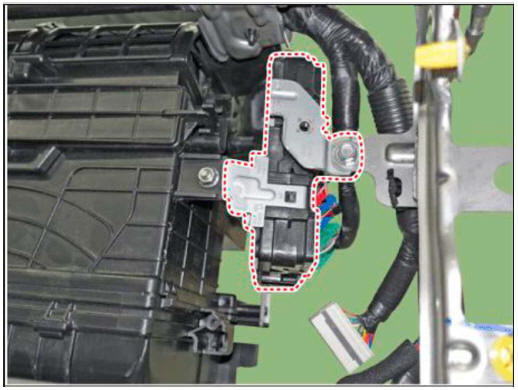
Hyundai Tucson: IBU (Integrated Body Control Unit (IBU)

The IBU manages all function related to :
- -"Start Stop Button (SSB) monitoring",
- "Immobilizer communication" (with Engine Management System unit for immobilizer release)
- Authentication server" (Validity of Transponder and in case of Smart Key option Passive Fob authentication )
- "System consistency monitoring"
- "System diagnosis"
- Control of display message / warning buzzer
The smart key unit masters the entire button engine start system.
In case of SMART KEY application, for example "Passive Access", "Passive Locking" and "Passive Authorization are integrated for Terminal switching Operations".It collects information about vehicle status from other modules (vehicle speed, alarm status, driver door open...), reads the inputs (e.g. SSB. Capacitive Sensor / Lock Button, PARK position Switch), controls the outputs (e.
g. exterior and interior antennas), and communicates with others devices via the CAN network as well as a single-line interfaces.
The diagnosis and learning of the components of the BES System are also handled by the SMK.
The SMK manages the functions related to the "terminal control" by activating external relays for ACC, IGN1 and IGN2. This unit is also responsible for the control of the STARTER relay.
The SMK is also controlling the illumination of the SSB as well as the "system status indicator", which consists of 2 LEDs of different color. The illumination of the fob holder is also managed by the SMK.
The SMK reads the inputs (Engine fob in, vehicle speed, relays contact status), controls the outputs (Engine relay output drive), and communicates with others devices via the CAN.
The internal architecture of the SMK is defined in a way that the control of the terminal is secured even in case of failure of one of the two microcontrollers, system inconsistency or interruption of communication on the CAN network.
In case of failure of one of the two controllers, the remaining controller shall disable the starter relay. The IGN1 and IGN2 terminals relays shall be maintained in the state previously memorized before the failure and the driver shall be able to switch those IGN terminals off by pressing the SSB with EMERGENCY_STOP pressing sequence. However, engine restart will not be allowed. The state of the ACC relay will depend on the type of failure.
The main functions of the SMK are :
- Control of Terminal relays
- Monitoring of the Vehicle speed received from sensor or ABS/ESP ECU.
- Control of SSB LEDs (illumination, clamp state).
- Control of the base station located in SSB through direct serial interface.
- System consistency monitoring to diagnose SMK failure and to switch to relevant limp home mode.
- Providing vehicle speed information
- Start Stop Button (SSB) monitoring
- Starter power control
READ NEXT:
 Start/Stop Button (SSB)
A single stage push button is used for the driver to operate the vehicle.
Pressing this button allows:
To activate the power modes ' O f f . 'Accessory', 'Ignition' and
'Start' by switching the corresponding t
 Wireless Power Charger System
Description and
Operation
Wireless Power Charger System
During ACC or IG ON, battery voltage is supplied to the wireless power
charger system to transmit an output of 5 W to mobile
phone.
Mobile phones certified with the wireless charging st
 System Configuration Diagram
Instrument cluster : Alerts about contact with mobile phone
IBU unit: Determines contact with mobile phone
Wireless charging lamp : Displays the charging status
SMK unit: Stops charging during the activation of LF
Major Functions of W
SEE MORE:
 Injector - Description
The GDI injector is similar to a standard injector, but sprays fuel at a much
higher pressure directly
into the combustion chamber and has a swirl disc to get the fuel swirling as it
exits the nozzle. This
aids in atomization of the fuel.
Th
 Engine compartment
„Smartstream G2.5 GDI
The actual engine compartment in the vehicle may differ from the
illustration
Engine coolant reservoir
Brake fluid reservoir
Air cleaner
Engine oil dipstick
Engine oil filler cap
Windshield washer fluid
Information
- Home
- Hyundai Tucson - Fourth generation (NX4) - (2020-2023) - Owner's Manual
- Hyundai Tucson - Fourth generation (NX4) - (2020-2023) - Workshop Manual