Hyundai Tucson: Wireless Power Charger System
Hyundai Tucson - Fourth generation (NX4) - (2020-2023) - Workshop Manual / Body Electrical System / Wireless Power Charger System
Description and Operation
Wireless Power Charger System
During ACC or IG ON, battery voltage is supplied to the wireless power charger system to transmit an output of 5 W to mobile phone.
Mobile phones certified with the wireless charging standard WPC (Qi 1.1.2) or equipped with an exclusive wireless charging case can be used.
WARNING
- WPC : Wireless Power Consortium
- Qi 1.1.2 : refers to certified product with the capability to transmit power of up to 5 W and detect metal and other impurities to prevent heating.
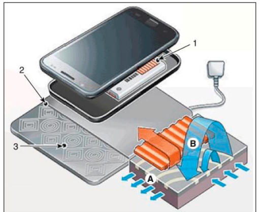
- Power receiver
- Charging pad
- Coil *
- Power receiver : embedded with the secondary coil designed to receive the induced current from the charging pad.
- Charging pad : electrical coils wound inside the plastic cover.
- Coil: Rectangular and circular coils generate diverse electromagnetic fields.
1)Connect power to the charging pad to generate electromagnetic fields in the coil.
2) Current induced from electromagnetic induction phenomenon is sent to the power receiver to charge the battery.
READ NEXT:
 System Configuration Diagram
Instrument cluster : Alerts about contact with mobile phone
IBU unit: Determines contact with mobile phone
Wireless charging lamp : Displays the charging status
SMK unit: Stops charging during the activation of LF
Major Functions of W
Wireless power charging
Components
Wireless power charging unit
Wireless power charging lamp
Troubleshooting
Wireless Power Charger System Troubleshooting
R-l. Check the wireless power charger system operation
If the placement of a mobile phone is not
Diagnosis With Diagnostic Tool
In the body electrical system, failure can be quickly diagnosed by using
the vehicle diagnostic system (diagnostic tool).
The diagnostic systemf diagnostic tool) provides the following information.
(1) Fault Code Searching : Checking fai
SEE MORE:
Crash pad center panel
Component Location
Crash pad center panel
Replacement
WARNING
When piying with a flat-tip screwdriver, wrap it with
protective tape, and apply protective tape
around the related parts, to prevent damage.
Put on gloves to protec
Ambient Temperature Sensor (ATS)
Description
Ambient Temperature Sensor (ATS) is installed on the front-end module and
senses the ambient
temperature.
This sensor is exposed to the ambient air temperature in front of the radiator.
The ATS is a Negative Temperature Coeffici
Information
- Home
- Hyundai Tucson - Fourth generation (NX4) - (2020-2023) - Owner's Manual
- Hyundai Tucson - Fourth generation (NX4) - (2020-2023) - Workshop Manual
