Hyundai Tucson: Diagnosis With Diagnostic Tool
Hyundai Tucson - Fourth generation (NX4) - (2020-2023) - Workshop Manual / Body Electrical System / Wireless Power Charger System / Diagnosis With Diagnostic Tool
- In the body electrical system, failure can be quickly diagnosed by using
the vehicle diagnostic system (diagnostic tool).
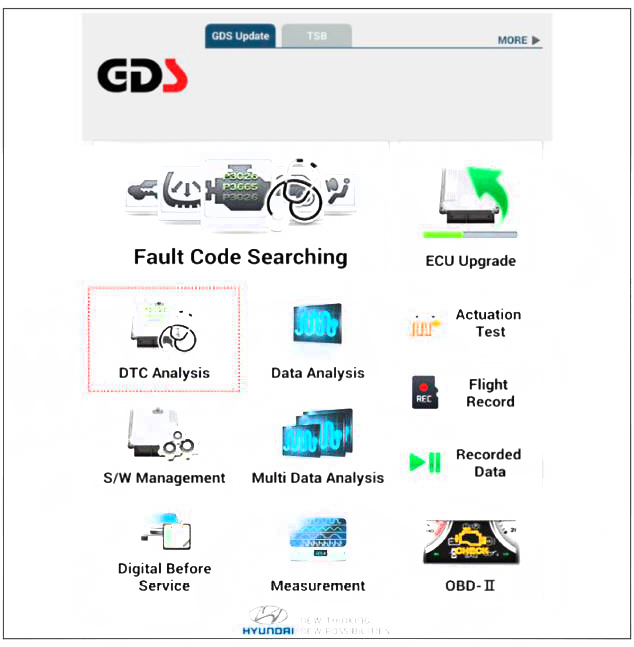
The diagnostic systemf diagnostic tool) provides the following information.
(1) Fault Code Searching : Checking failure and code number (DTC)
(2) Data Analysis : Checking the system input/output data state
(3) Actuation test: Checking the system operation condition
(4) S/W Management: Controlling other features including system option setting and zero point adjustment
- If diagnose the vehicle by diagnostic tool, select "DTC Analysis" and "Vehicle".

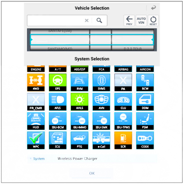
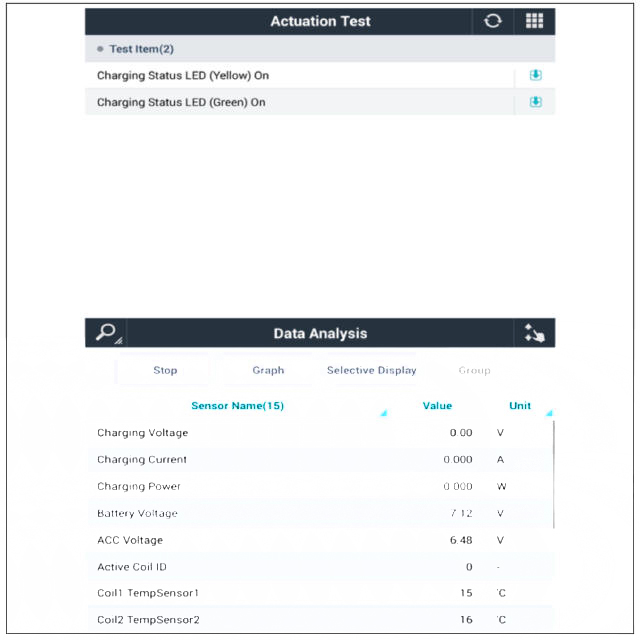
- Select the 'WPC' to search the current state of the input/output data.

- To forcibly actuate the input value of the module to be checked, select option 'Actuation Test'.
Removal
WARNING
Handling wireless charging system parts by wet hands may cause electric shock.
- Disconnect the negative (-) battery terminal.
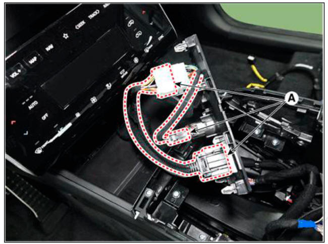
- Remove the floor console tray assembly (A).
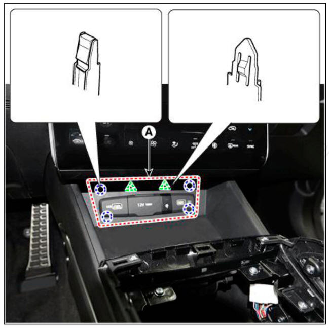
- Disconnect the floor console tray connectors (A).
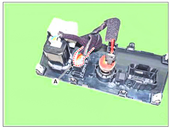
- Disconnect the wireless charging lamp connector (A).
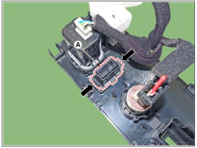
- Remove the wireless charging lamp (A).
Installation
- Install the wireless charging lamp.
- Connect the wireless charging lamp connector.
- Install the floor console tray assembly.
- Connect the negative (-) battery terminal.
READ NEXT:
 Ignition Switch Assembly
Removal
Disconnect the negative (-) batteiy terminal.
Remove the steering column upper and lower shrouds.
(Refer to Body - "Steering Column Shroud Panel")
Remove the ignition switch (A) after disconnecting the 6P connector (B).
Anti-theft System (UK only)
Components Location
UIP(Ultrasonic Intrusion Protection) Sensor
UIP(Ultrasonic Intrusion Protection) Siren
Description
Anti Theft Device
Block Diagram
This system is designed to provide protection from unauthorised entry into
th
SEE MORE:
LCD display control
The LCD display modes can be changed by using the control buttons.
MODE button for changing modes
MOVE switch for changing items
SELECT/RESET button for setting
or resetting the selected item
Information
When the infotainment system
Oil Pump Chain
Disconnect the battery negative terminal.
Remove the timing chain.
(Refer to Timing System - "Timing Chain")
Remove the oil pump chain tensioner (A).
Tightening torque :
9.8 - 11.8 N.m (1.0 - 1.2 kgf.m, 7.2 - 8.7 lb-ft)
Information
- Home
- Hyundai Tucson - Fourth generation (NX4) - (2020-2023) - Owner's Manual
- Hyundai Tucson - Fourth generation (NX4) - (2020-2023) - Workshop Manual
