Hyundai Tucson: Anti-theft System (UK only)
Components Location

- UIP(Ultrasonic Intrusion Protection) Sensor
- UIP(Ultrasonic Intrusion Protection) Siren
Description
Anti Theft Device
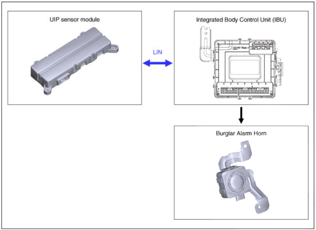
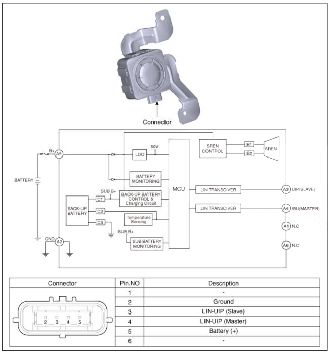
Block Diagram
This system is designed to provide protection from unauthorised entry into the vehicle.
This system is operated in three stages : the first is the "Armed" stage, the second is the "Theft-alarm" stage, and the third is the "Disarmed" stage.
If triggered, the system provides an audible alarm with blinking of the hazard warning lights.
System Overview
- UIP sensor Module (UIP sensor & G sensor)
- Monitors vehicle interior for intrusion with ultrasonic wave.
- Monitored area is limited to interior of the vehicle.
- Monitors vehicle tilt with tilt sensor.
- Tilt is monitored on all 4 tires as well as the entire vehicle.
- Intrusion Detection System Normal Operation Condition
- UIP Sensor Module Self-diagnosis: If DISARM signal is received from IBU. UIP Sensor Module performs selfdiagnosis (UIP Sensor Module normal operation test), and the result of the diagnosis is sent to IBU for 1 second.
- UIP Sensor Module enters Intrusion Detection Mode if all of the
following conditions are satisfied.
1) If UIP Sensor Module self-diagnosis data sent to IBU is normal.
2) UIP OFF Switch Status: Disabled 3) ARM Mode signal is received from IBU
- I f intrusion or tilt is detected while in Intrusion Detection Mode. UIP Sensor Module sends alarm signal to IBU. and IBU activates the alarm horn.
- Alarm is deactivated with DISARM signal from IBU.
- Intrusion Detection System Disable Conditions
- UIP Sensor Module does not enter Intrusion Detection Mode even if ARM Mode signal is received from IBU.
1) If UIP Sensor Module self-diagnosis data sent to IBU is not normal.
2) UIP OFF Switch Status : Enabled
Function
- Siren
(1) Power On-Off
It is necessary to apply voltage to the SIREN to power-on the SIREN.The SIREN saves its status into the internal memory. Before removing the car battery supply or SIREN Sensors connector. Take care that the system is in DISARM state otherwise it will start to sound using the internal batteiy.
(2) Arming-Disarming
The system is armed by IPM specific command on LIN BUS
Conditions to ARM the SIREN
- System m DISARM STATE
- IGN OFF
The system is disarmed by IPM specific command on LIN BUS
Conditions to ARM the SIREN
- System in ARM STATE
- System in ALARM STATE
(3) Arming Disarming signaling
The IPM manages the blinker activation during DISARM to ARM. ARM to DISARM and ALARM to DISARM transition.
(4) Functional States
- DISARM STATE
In this state the vehicle is not protected
- Pre ARM INHIBITION Time
The Pre ARM or INHIBITION TIME starts when the SIREN receives an ARM command by IPM.
If one or more protections are active during DISARM ARM transition or during the inhibition time, the SIREN exclude it automatically!except for UIP and TILT sensor). It will be re-included in the protection when it will return in the correct condition A continuous low power sound indicated the exclusion during Pre Arm INHIBITION time.
The INHIBITION Time duration is 30 sec starting from DISARM to ARM transition.
- ARM STATE
In this state the vehicle is fully protected
- Partical ARM STATE
In this state the vehicle is not fully protected : the UIP and TILT sensor are excluded.
- ALARM STATE
In this state the SIREN is sounding using vehicle batteiy if present, otherwise its internal.
- ALARM PAUSE STATE
The ALARM PAUSE STATE is a state among two consecutive ALARM STATE
(5) Stabilization Time
The Stabilization Time is the time that the external sensor(UIP and TILT) need to stabilize the function when system are armed. The Stabilization tune duration for UIP and TILT sensor is 30 sec starting from DISARM to ARM transition.
(6) Alarm Causes
The SIREN activates the sound and send to the IPM a LIN BUS command to activate the blinker.
When an alarm condition is detected in ARM STATE
- PARAMETRIC by LIN BUS command
- IGN Key by LIN BUS command
- EXTERNAL SENSOR by COBRA BUS command
- VEHICLE BATTERY TAMPERING by POWER SUPPLY Monitoring
- COBRA BUS TAMPERING FUNCTION by heartbeat Monitoring
If the alarm cause is not removed, the ALARM CYCLE is repeated after an ALARM PAUSE.
The ALARM CYCLE duration is 27+-0.5 sec and ALARM PAUSE is 5=0.5 sec.
During the ALARM CYCLE, it is possible to DISARM by IPM specific LIN BUS command.
(7) Protection
- PERIMETRIC - IGN KEY
The SIREN protects the vehicle against perimetric opening and ignition key activation attempts.
The IPM sends a specific command to the SIREN if a door/hood/tgate are opened or theignition is turn-on.
If the SIREN is in ARM state or PARTIAL ARM state, it goes to ALRAM state. If the alarm condition remains the SIREN will go again to the ALARM state until the alarm counter is rolled off(total 9 ALARM cycles of 27.5sec and 8 ALARM pause of 5sec. internal memory default)
- Cobra BUS Tampering
If the communication is interrupted during ARM State, the SIREN goes to ALARM stateThe the alarm condition remains, the SIREN will goes again to ALARM state until the alarm counter is rolled off(total 9 ALARM cycles of 27.5sec and 8 ALARM pause of 5sec, internal memory default)
- Vehicle Batteiy Tampering
If one or both power supply wire(B+ and/or GND) are removed during ARM state or PARTIAL ARM state,the SIREN goes to ALARM state.
The the alarm condition remains, the SIREN will goes again to ALARM state until the alarm counter is rolled off (total 8 ALARM cycles of 26ec and 7 ALARM pause of Msec, internal memory default)
- Internal Batteiy Connection
The SIREN is a self-powered system with internal back-up battery(primary lithium type Typical capacity 1400mAh) The external power supply is always monitored and the behaviour of the system will change According to the following table.
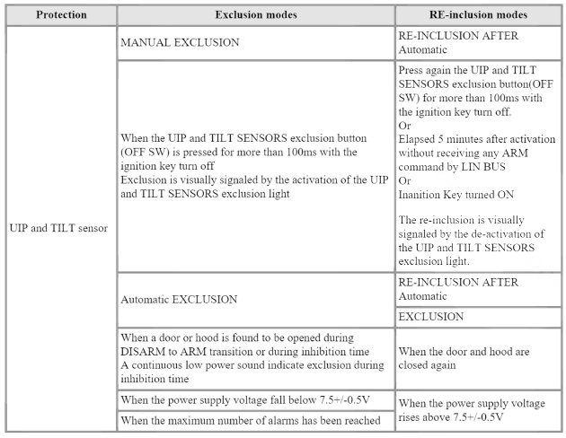
(8) Protections exclusion
(9) Blinker
The SIREN drives the blinker during ALARM state by a specific LIN BUS command
Schematic Diagram

Removal
- Disconnect the negative (-) battery terminal.
- Remove the overhead console.
(Refer to Lighting System - "Overhead Console Lamp")
WARNING
- Be careful not to get object or debris on the ultrasonic sensor.
- Do NOT place object in front of the sensor.
- If UIP Sensor Module OFF Switch is pressed, then the UIP Sensor Module is turned OFF, and intrusion and tilt monitoring are disabled
- To enable to monitoring functions, you must first Unlock with Remote Keyless Entry (RKE), then activate via OFF SW (Indicator OFF), or by switching to IGN Key ON.
- If you leave the vehicle with moving pet or object in the vehicle, be sure to turn the UIP Sensor Module OFF. then Lock with Remote Keyless Entry (RKE).
Installation
- To install, reverse removal procedure.
Schematic Diagram
Removal
- Disconnect the negative (-) battery terminal.
- Remove the luggage side trim LH (Refer to Body - "Luggage Side Trim")
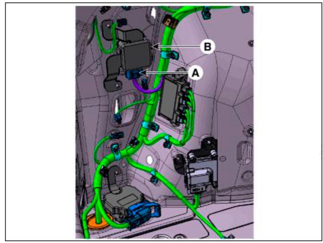
- Disconnect the UIP siren connector (A)
- Loosen the mounting nuts and remove the UIP siren (B).
Installation
- To install, reverse removal procedure.
READ NEXT:
SEE MORE:
 Shift Lever
Removal
Turn ignition switch OFF and then disconnect the battery (-) cable.
Remove the floor console assembly.
(Re fer to Body (Interior and Exterior) - " Floor Console")
Remove the floor air duct (A).
Separate the wi
Manual heating and air conditioning
Start the engine.
Set the mode to the desired position.
For improving the effectiveness of
heating and cooling, select:
Heating:
Cooling:
Set the temperature control to the
desired position.
Set the air intake contr
Information
- Home
- Hyundai Tucson - Fourth generation (NX4) - (2020-2023) - Owner's Manual
- Hyundai Tucson - Fourth generation (NX4) - (2020-2023) - Workshop Manual
