Hyundai Tucson: Start/Stop Button (SSB)
A single stage push button is used for the driver to operate the vehicle. Pressing this button allows:
- To activate the power modes ' O f f . 'Accessory', 'Ignition' and 'Start' by switching the corresponding terminals
- To start the engine
- To stop the engine
The contact will be insured by a micro-switch and a backlighting is provided to highlight the marking of the button whenever necessary.
Three (3) LED colors are located in the outside ring of the switch assy. They display the status of the system.
They are OFF(White) / ACC(Amber) / ON(Green).
BESfButton Engine Start) System State Chart
System STATES in LEARNING MODE
In learning mode, the BES System can be set in 6 different states, depending
on the status of the terminals and Engine status:
Referring to the terminals, the system states described in the table above are the same as those found in a system based 011 a mechanical ignition switch.
One of the features distinctive from the Mechanical Ignition Switch-based system is that the BES system allows specific transition from OFF to START without going through ACC and IGN states.
System STATES IN VIRGIN MODE
The BES System can be set in 5 different states (OFF LOCKED is not available
in virgin mode), depending on the status of the
terminals and Engine status : 
Referring to the terminals, the system states described in the table above are the same as those found in a system based 011 a mechanical ignition switch.
One of the features distinctive from the Mechanical Ignition Switch-based system is that the BES system allows specific transition from OFF to START without going through ACC and IGN states.
Removal
- Disconnect the negative (-) battery terminal.
- Remove the cluster fascia panel.
(Refer to Body - "Cluster Fascia Panel")
- Remove the front monitor.
(Refer to AVN System - "Front Monitor")
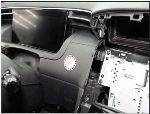
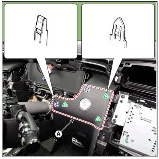
- Using a remover and remove the crash pad garnish CTR.
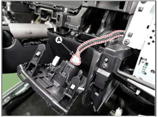
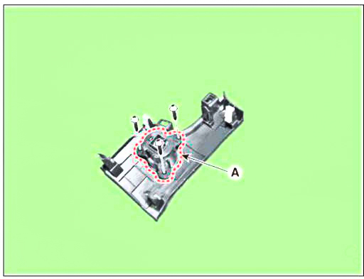
- Disconnect the start / stop button connector (A).
- Loosen the mounting screws and remove the start / stop button (A).
Installation
- Install the start / stop button.
- Install the crash pad garnish CTR.
- Install the front monitor.
- Install the cluster fascia panel.
READ NEXT:
 Wireless Power Charger System
Description and
Operation
Wireless Power Charger System
During ACC or IG ON, battery voltage is supplied to the wireless power
charger system to transmit an output of 5 W to mobile
phone.
Mobile phones certified with the wireless charging st
System Configuration Diagram
Instrument cluster : Alerts about contact with mobile phone
IBU unit: Determines contact with mobile phone
Wireless charging lamp : Displays the charging status
SMK unit: Stops charging during the activation of LF
Major Functions of W
Wireless power charging
Components
Wireless power charging unit
Wireless power charging lamp
Troubleshooting
Wireless Power Charger System Troubleshooting
R-l. Check the wireless power charger system operation
If the placement of a mobile phone is not
SEE MORE:
Supplemental Restraint System Control Module (SRSCM)
Components Location
Supplemental Restraint System Control Module (SRSCM)
Supplemental Restraint System Control Module (SRSCM)
Removal
Disconnect the battery negative terminal.
WARNING
After disconnecting the cables
External Control Valve Compressor Inspection (GDS)
Compressor type: Fixed type compressor, External control valve, Internal
control valve.
In cases of fixed type and internal control valve, it is possible to inspect
compressor's operation with clutch noise.
When it comes to External con
Information
- Home
- Hyundai Tucson - Fourth generation (NX4) - (2020-2023) - Owner's Manual
- Hyundai Tucson - Fourth generation (NX4) - (2020-2023) - Workshop Manual
