Hyundai Tucson: Fan motor
- Turn ignition switch "OFF" and connect the diagnostic tool to the Data Link Connector.
- With the gear shift in P (Park) position and ignistion switch "ON" (LED of the Power button illuminates in Red), select the "force drive" function.
- Force drive the cooling fan motor.
- Start the "Fan motor low speed" of the force drive function.

- Press the start button and force drive for 5 seconds.
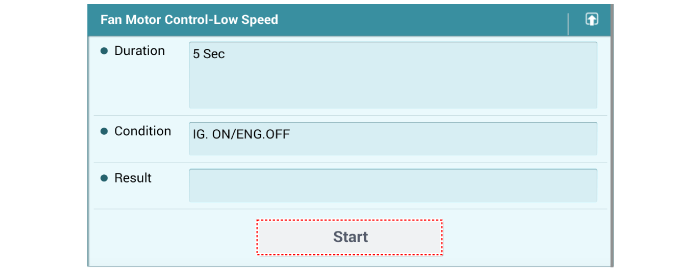
- Visually check the operation of the cooling fan.
Removal and Installation
- Disconnect the negative battery terminal.
- Drain the coolant.
(Refer to Cooling System - "Coolant")
- Remove the front bumper beam.
(Refer to Body(Interior and Exterior) - "Front Bumper Beam Assembly")
- Remove the hood latch.
(Refer to Body (Interior and Exterior) - "Hood Latch")
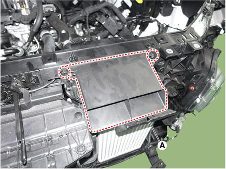
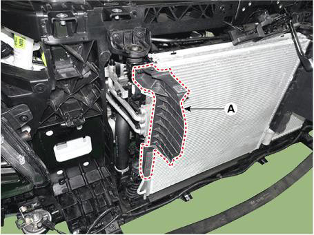
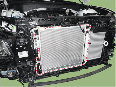
- Remove the air intake shield (A).
Tightening torque : 7.8 - 11.8 Nm (0.8 - 1.2 kgf.m, 5.8 - 8.7 lb-ft)
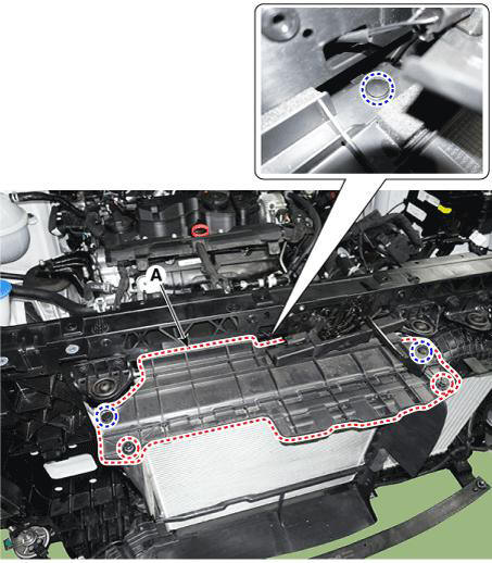
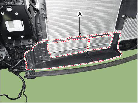
- Remove the radiator upper air guard (A).
Tightening torque : 7.8 - 11.8 Nm (0.8 - 1.2 kgf.m, 5.8 - 8.7 lb-ft)
- Remove the radiator side air guard (A).
Tightening torque : 7.8 - 11.8 Nm (0.8 - 1.2 kgf.m, 5.8 - 8.7 lb-ft)
LH
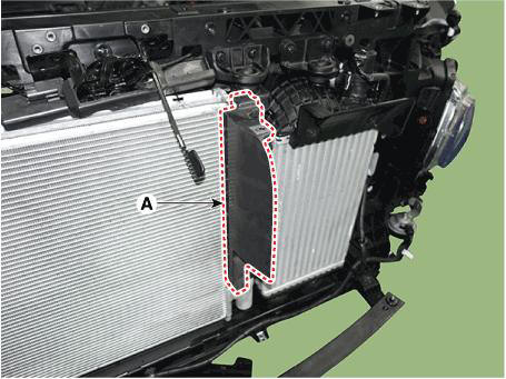
RH
- Remove the air dam (A).
Tightening torque : 7.8 - 11.8 Nm (0.8 - 1.2 kgf.m, 5.8 - 8.7 lb-ft)
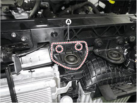
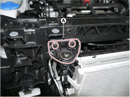
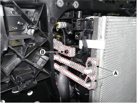
- Remove the radiator upper mounting bracket (A).
Tightening torque : 7.8 - 11.8 Nm (0.8 - 1.2 kgf.m, 5.8 - 8.7 lb-ft)
RH
LH
- Air conditioner refrigerant is recovered by recovery/regeneration/charger.
(Refer to Heating,Ventilation And Air Conditioning - "Air conditioning System")
- Remove the RH head lamp assembly.
(Refer to Body Electrical System - "Lighting System")
- Loosen the refrigerant line pipe (A) mounting nuts and bracket mounting bolt (B).
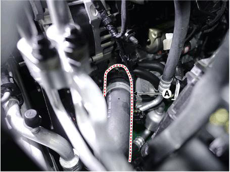
- Disconnect the radiator upper hose (A) and degassing hose (B) from radiator.
- Disconnect the radiator lower hose (A) from the inlet fitting.
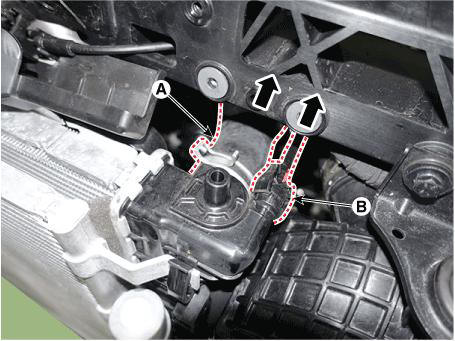
- Disconnect the cooling fan connector (A).
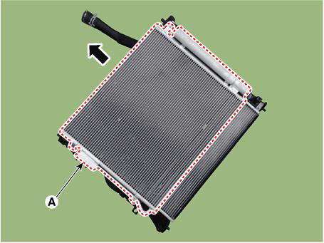
- Remove the radiator assembly (A) from the vehicle.
- Remove the condenser (A) by push up from the radiator.
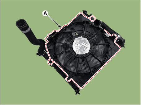
- Remove the cooling fan (A).
Tightening torque : 4.9 - 7.8 N.m (0.5 - 0.8 kgf.m, 3.6 - 5.8 lb-ft)
- Install in the reverse order of removal.
- Fill with engine coolant.
(Refer to Cooling System - "Coolant")
WARNING
The coolant must be injected according to the integrated thermal management module (ITM) coolant filling method.
- Start engine and check for leaks.
Inspection
Radiator Leakage Test
- Wait for the engine to cool. Carefully remove the coolant reservoir tank cap and fill the radiator with engine coolant. Then, install it on the pressure tester.
- Apply a pressure tester to the radiator and apply a pressure of 125.3 - 154.7 kPa (1.28 - 1.58 kgf/cm², 22.44 - 18.17 psi).
- Inspect for engine coolant leaks and a drop in pressure.
- Remove the tester and reinstall the radiator cap.
WARNING
Check for engine oil in the coolant and/or coolant in the engine oil.
Description
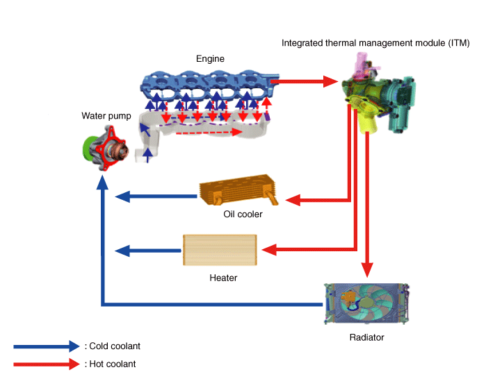
Integrated thermal management module (ITM) is a device that controls the coolant flow rate according to coolant temperature. At initial startup, the integrated thermal management module (ITM) quickly warms up the engine by controlling the flow of the coolant and this fast warm-up helps improve the fuel efficiency. When the coolant temperature rises, the integrated thermal management module (ITM) adjusts the cooling water temperature by controlling the valves to regulate the flow of coolant through a radiator or heater.
READ NEXT:
 Integrated Thermal Management Module (ITM)
Components
Integrated thermal management module (ITM)
Heater pipe
Heater hose
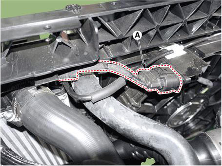
Turbo charger coolant hose
Heater pipe A
Heater pipe A gasket
Oil cooler hose A
Oil cooler pipe
Integrated Thermal Management Module (ITM)
WARNING
Heater Pipe
Disconnect the battery negative terminal.
Remove the engine cover.
(Refer to Engine and Transaxle Assembly - "Engine Cover")
Remove the engine room under cover.
(Refer to Engine and Transaxle Assembly - "Engine Room Unde
Oil cooler pipe
Remove the heater pipe
Disconnect the oil cooler hose (A) from the ITM.
Disconnect the oil cooler hose (A) from the oil cooler.
Rmove the oil cooler pipe (A) after loosening the mounting bolts.
Tightening torque :
9.8 - 1
SEE MORE:
Cylinder Block - Removal and Installation
Remove the cylinder head.
(Refer to Cylinder Head Assembly - "Cylinder Head")
Remove the RH water jacket insert and LH water jacket insert (A).
WARNING
When removing the water jacket insert, Be careful not to damage the
IMT System Actuator
Components and Components Location
IMT system actuator
Connector and Terminal Information
Circuit Diagram
Information
- Home
- Hyundai Tucson - Fourth generation (NX4) - (2020-2023) - Owner's Manual
- Hyundai Tucson - Fourth generation (NX4) - (2020-2023) - Workshop Manual
