Hyundai Tucson: Electric WGT Control Actuator- Installation
Hyundai Tucson - Fourth generation (NX4) - (2020-2023) - Workshop Manual / Engine Control - Fuel System / Electric WGT Control Actuator / Electric WGT Control Actuator- Installation
WARNING
- When replacing the Electric WGT Control Actuator, perform the rod adjustment procedure.
- When install the electric WGT control actuator, do not reuse a C-Ring.
- Install in the reverse order of removal.
Adjustment
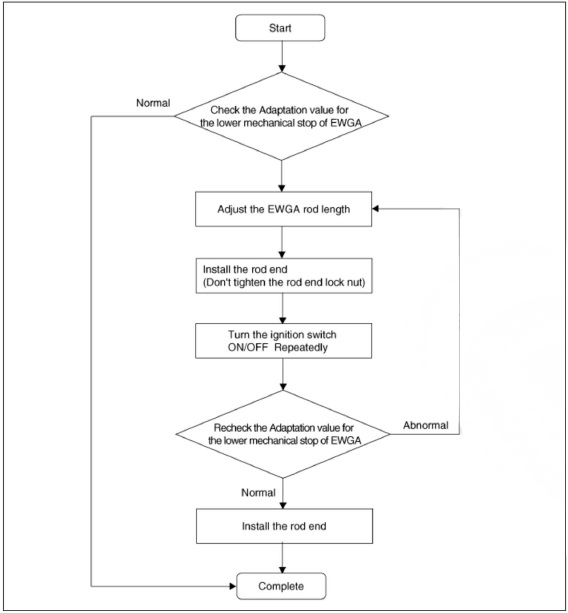
Rod Adjustment Procedure Flowchart
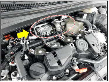
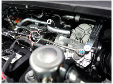
- Check that the waste gate turbo charger is coolenough to work.
WARNING
- Use an electric fan to cool down fast.
- The cooling part (A) and the wind direction (B) areas follows.
- Turn the ignition switch to OFF position.
- Connect the diagnostic tool to DLC connector (16pin) under the driver side instrument panel.
- Turn the ignition switch ON.
WARNING
Do not start the engine.
- Select VIN or Vehicle on the initial screen.
- Enter "Engine Control" menu after slelecting vehicleinformation (Vehicle model. Model year. Engine type)or entering the VIN number.
- Select the "Current Data".
- Without starting the engine, repeatedly turn theignition ON for 5
seconds and OFF for 5 seconds.and then check the
"Adaptation value for lowmechanical stop of EWGA" on the diagnostic tool.
Repeat this step until the amount of difference in theadaptation value from the previous cycle is below 0.05 V.
WARNING
Do not start the engine. This is a crucial step toread the correct adaptation value.
- Check that "Adaptation value for the lower mechanical stop of EWGA" is within the specified voltage value.
Voltage : 3.5 - 3.7V
- If the measured voltage value is not within the specified voltage value, ad just the EWGA rodlength. Otherwise, no further procedure is required.
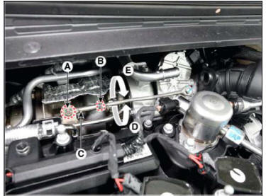
(1) Loosen the rod end lock nut (B) and remove the C-ring (A).
(2) Adjust the rod end part (C) by rotating it clockwise (D) or counterclockwise (E) to satisfy the specification.
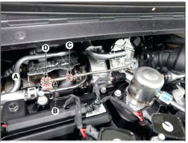
- Install the rod end (B) to the turbocharger lever (A) temporarily. Do not tighten the rod end lock nut (C) and C-ring (D).
- Check the "Adaptation value for the lower mechanical stop of EWGA" after selecting "Current Data" menu. Turn the ignition switch ON/OFF repeatedly until the changing value of the "Adaptation value for the lower mechanical stop of EWGA" is within 0.05V.
WARNING
Turn the ignition switch ON/OFF. But hold 5 seconds at each IG ON or OFF state.
- If the measured voltage value is not within the specified voltage value, repeat procedures 9 - 1 2 until the voltage value is within the specified voltage value.
- If it is within the specified voltage value, install the rod end to the turbocharger lever.
(1) Install the rod end (B) to the turbocharger lever (A) temporarily.
(2) Fix the C-ring (C).
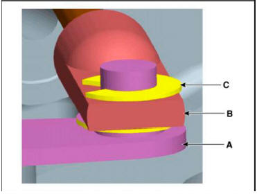
- Install the 0.6mm filler gauge between EWGA lever (A) and rod end (B).
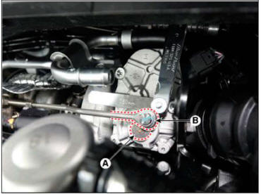
- Tighten the lock nut (A).
READ NEXT:
 RCV Control Solenoid Valve
Description
RCV (Recirculation Valve) Control Solenoid Valve is installed on the
intercooler inlet pipe and
operates the RCV actuator which controls the by-pass passage of the turbocharger
compressor.When
the throttle is closed, while the engi
Electric Exhaust Gas Re-circulation (EEGR) Control Valve
Description
The Electric EGR Control Valve is installed in between the EGR cooler and the
exhaust line and is a
solenoid valve. This valve controls EGR (Exhaust Gas Recirculation) amount by
the ECM's duty
control signal depending on engine
Integrated Thermal Management Module (ITM)
Description
Integrated Thermal Management Module (ITM) is a device that controls the
coolant flow rate according to coolant
temperature. At initial startup, the ITM quickly warms up the engine by
controlling the flow of the coolant and this fas
SEE MORE:
ABS Does Not Operate/ ABS Does Not Operate (Intermittently)
ABS Does Not Operate
Detecting condition
Brake operation varies depending on driving conditions and road surface
conditions, so diagnosis can be difficult. However if a normal DTC is
displayed, check the following probable cause. When the problem
Trip computer (Type B)
The trip computer is a microcomputercontrolled
driver information system that
displays information related to driving.
Information
Some driving information stored in the
trip computer (for example Average
Vehicle Speed) resets if the battery is
Information
- Home
- Hyundai Tucson - Fourth generation (NX4) - (2020-2023) - Owner's Manual
- Hyundai Tucson - Fourth generation (NX4) - (2020-2023) - Workshop Manual
