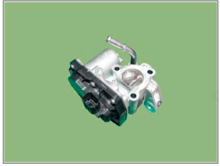
Hyundai Tucson: Electric Exhaust Gas Re-circulation (EEGR) Control Valve
Hyundai Tucson - Fourth generation (NX4) - (2020-2023) - Workshop Manual / Engine Control - Fuel System / Electric Exhaust Gas Re-circulation (EEGR) Control Valve
Description
The Electric EGR Control Valve is installed in between the EGR cooler and the exhaust line and is a solenoid valve. This valve controls EGR (Exhaust Gas Recirculation) amount by the ECM's duty control signal depending on engine load and the need of intake air.
The Exhaust Gas Recirculation (EGR) system is used to add the exhaust gas to intake air in order to reduce an excess of air and the temperature in the combustion chamber.
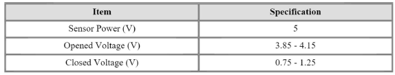
Specification
Motor

Position Sensor
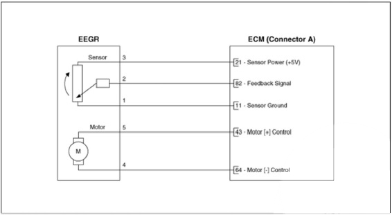
Circuit Diagram
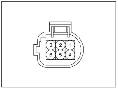
Harness Connector
Inspection
Motor
- Turn the ignition switch OFF.
- Disconnect the EEGR valve connector.
- Check that the EEGR valve is stuck by foreign material.
- Measure resistance between motor 4 and 5 control terminals of the motor.
- Check that the resistance is within the specification

Feedback Position Sensor
- Connect the diagnostic tool to the data link connector.
- Perform the fully open and the fully closing operation of the EEGR valve by using the actuation test.
- Check that the voltage is within the specification.

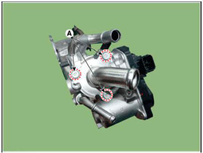
Removal
- Turn the ignition switcg OFF, and disconnect the batteiy negative (-) terminal.
- Remove the EGR cooler.
(Refer to Engine Mechanical System - "EGR Cooler")
- Remove the EEGR control valve after loosening the mounting bolt (A).
Tightening Torque : 18.6 - 23.5 N.m (1.9 - 2.4 kgf.m, 13.7 - 17.3 lb-ft)
Installation
WARNING
- Install the component with the specified torques.
- Note that internal damage may occur when the component is dropped. In this case, use it after inspecting.
- Use care to keep foreign material out of the component.
- Install in the reverse order of removal.
READ NEXT:
 Integrated Thermal Management Module (ITM)
Description
Integrated Thermal Management Module (ITM) is a device that controls the
coolant flow rate according to coolant
temperature. At initial startup, the ITM quickly warms up the engine by
controlling the flow of the coolant and this fas
CCWD Actuator- Description
Description
CVVD(Continuous Variable Valve Duration) System is a device to control the
optimum open and
close timing according to the driving mode by changing the valve opening section.
CVVD Actuator
Specification
Circuit Diagram
SEE MORE:
Clutch touch-point learning
WARNING
Clutch touch-point learning status can be checked through the
cluster lamp.
Prior to learning. "E" lamp turns on. After learning, the
current gear position (N) replaces the "E" lamp and blinks.
Check t
GPF Regeneration
This procedures is to forcibly regenerate the GPF with scan tool when the GPF
doesn't have been regenerated during driving. For
example, if the vehicle has repeated "Low speed driving" or "Short distance
driving", the GPF
Information
- Home
- Hyundai Tucson - Fourth generation (NX4) - (2020-2023) - Owner's Manual
- Hyundai Tucson - Fourth generation (NX4) - (2020-2023) - Workshop Manual
