Hyundai Tucson: Integrated Thermal Management Module (ITM)
Hyundai Tucson - Fourth generation (NX4) - (2020-2023) - Workshop Manual / Engine Control - Fuel System / Integrated Thermal Management Module (ITM)
Description
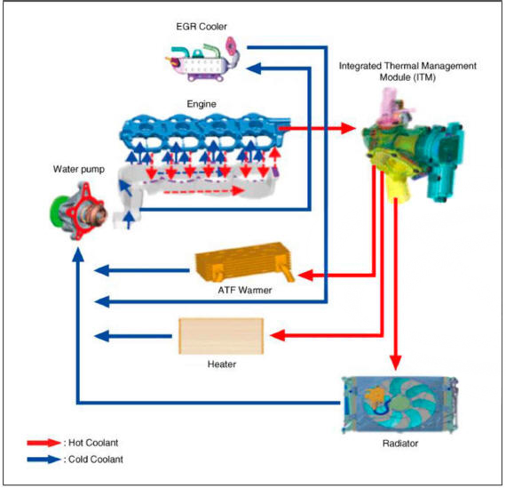
Integrated Thermal Management Module (ITM) is a device that controls the coolant flow rate according to coolant temperature. At initial startup, the ITM quickly warms up the engine by controlling the flow of the coolant and this fast warmup helps improve the fuel efficiency. When the coolant temperature rises, the ITM adjusts the cooling water temperature by controlling the valves to regulate the flow of coolant through a radiator or heater.
Components
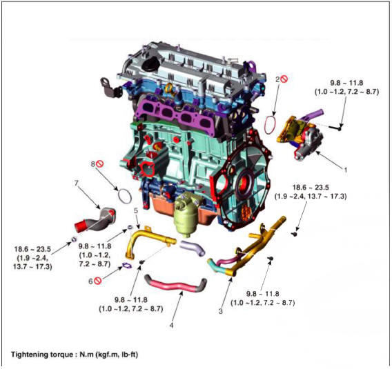
- Integrated thermal management module (ITM)
- Integrated thermal management module (ITM) O-ring
- Heater pipe B
- Heater water hose
- Heater pipe A
- Heater pipe A gasket
- Water inlet fitting
- Water inlet fitting gasket
Circuit Diagram
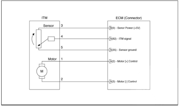
Harness Connector
Removal and Installation
- Remove the integrated thermal management module (ITM).
(Refer to Engine Mechanical System - "Integrated Thermal Management Module (ITM)")
WARNING
- A separate replacement of the ITM (Integrated Thermal
Management Motor) is not possible.
You should place the new ITM (Integrated Thermal Management Module) assembly to fix the problem.
- Install in the reverse order of removal.
Inspection
- Turn the ignition switch OFF.
- Connect the diagnostic tool to data link connector (DLC).
- Turn the ignition switch ON.
- Select the "Veichle, Model Year, Engine Specification, System".
- Connect a diagnostic tool and then operate the integrated thermal management motor (ITM).
- Confirm the Integrated thermal management motor (ITM) proper operation.
- When the DTC occur, refer to the DTC guide.
READ NEXT:
 CCWD Actuator- Description
Description
CVVD(Continuous Variable Valve Duration) System is a device to control the
optimum open and
close timing according to the driving mode by changing the valve opening section.
CVVD Actuator
Specification
Circuit Diagram
CCWD Actuator- Installation
WARNING
When installing the CVVD actuator the shaft gear do not fit
properly, rotate the C W D actuator in both directions and
installing it uaturally.
(Do not impact when installating the component.)
Do not damage to the component whe
SEE MORE:
Engine Control Module (ECM)
ECM Terminal And Input/Output signal
ECM Terminal Function
Connector A
Connector B
Engine Control Module (ECM) - Removal
Removal
Turn ignition switch OFF and disconnect the battery negative (-)
terminal
Tires and wheels
WARNING
Tire failure may cause loss of
vehicle control resulting in an
accident. To reduce risk of SERIOUS
INJURY or DEATH, take the
following precautions:
Inspect your tires monthly for
proper inflation as well as wear
and damage.
&nb
Information
- Home
- Hyundai Tucson - Fourth generation (NX4) - (2020-2023) - Owner's Manual
- Hyundai Tucson - Fourth generation (NX4) - (2020-2023) - Workshop Manual
