Hyundai Tucson: Diagnosis with Diagnostic tool
Hyundai Tucson - Fourth generation (NX4) - (2020-2023) - Workshop Manual / Advanced Driver Assistance System (ADAS) / Rear Corner Radar System / Diagnosis with Diagnostic tool
Components
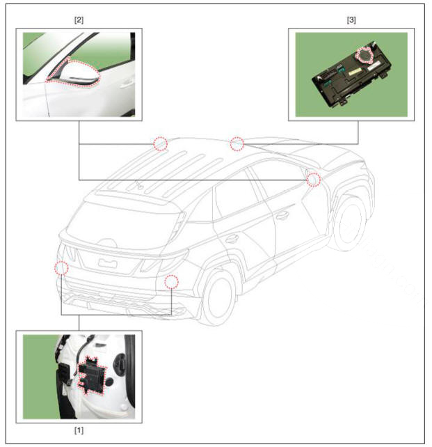
- Rear corner radar unit
- Warning indicator
- Speaker (Cluster)
Diagnosis with Diagnostic tool
- In the body electrical system, failure can be quickly diagnosed by using
the vehicle diagnostic system (Diagnostic tool).
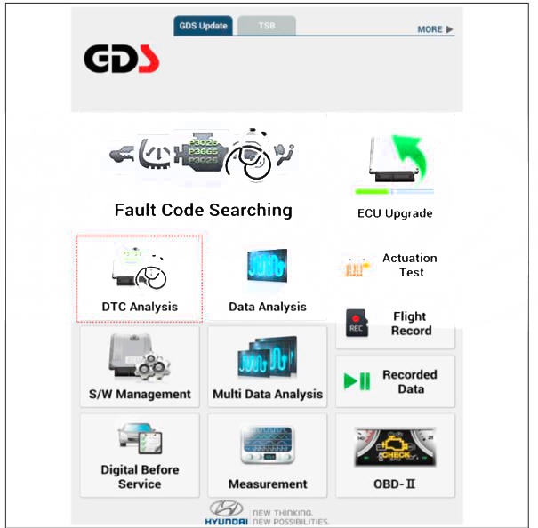
The diagnostic system (Diagnostic tool) provides the following information.
(1) Fault Code Searching : Checking failure and code number (DTC)
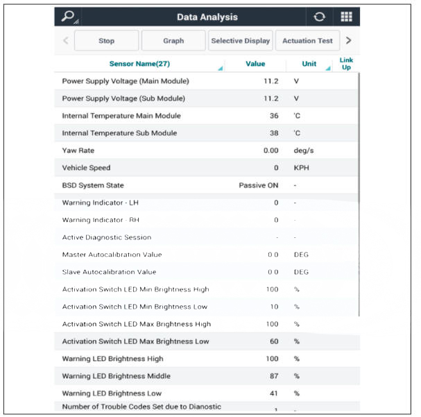
(2) Data Analysis : Checking the system input/output data state
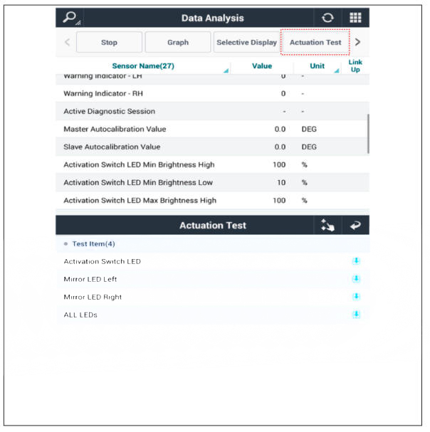
(3) Actuation test: Checking the system operation condition
(4) S/W Management: Controlling other features including system option setting and zero point adjustment
- Connect the cable of Diagnostic tool to the data link connector in driver side crash pad lower panel, and turn on the Diagnostic tool.
- If diagnose the vehicle by Diagnostic tool, select "DTC Analysis" and "Vehicle".
- If check current status, select the "Data Analysis"
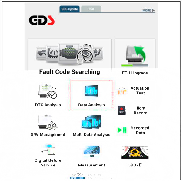
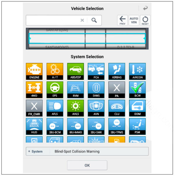
- Select "BCW", if you want to check current data of BCW system.
- If you want to check each module operation forcefully, select "Actuation test".
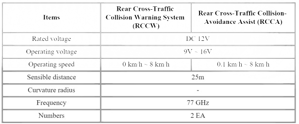
Specifications
BCW, BCA
RCCW, RCCA
SEW

READ NEXT:
 Connector and Terminal Function
Connector Funtion
Removal
Disconnect the negative (-) battery terminal.
Remove the rear bumper assembly.
(Refer to Body - "Rear Bumper Assembly")
Disconnect the rear corner radar connector (A).
Loosen the mounting n
Rear Corner Radar Calibration
Rear bumper accident vehicles and vehicles that replaced rear corner
radar units must perform rear corner radar unit alignment
using Diagnostic tool.
Connect the cable of Diagnostic tool to the data link connector in
driver side crash pa
Parking Distance Warning (PDW)
Description
PDW consists of 8 sensors (front: 4 units, rear : 4 units) that are used
to detect obstacles and transmit the result in three
separate warning levels, the first, second and third to IBU via LIN
communication.
IBU decides the
SEE MORE:
Heater - Inspection
Operating Logic Test (Manual only)
Inspect the PTC operation with the confirmation logic below :
Entering
(1) Set the mode to FLOOR.
(2) Set the temperature to MAX HOT.
(3) Turn off the blower switch.
(4) Press the intake (recirculat
Motor Driven Power Steering - Description
Description
MDPS (Motor Dirven Power Steering) system uses an electric motor to assist
the steering force and it
is an engine operation independent steering system.
MDPS control module controls the motor operation according to information
re
Information
- Home
- Hyundai Tucson - Fourth generation (NX4) - (2020-2023) - Owner's Manual
- Hyundai Tucson - Fourth generation (NX4) - (2020-2023) - Workshop Manual
