Hyundai Tucson: Parking Distance Warning (PDW)
Description
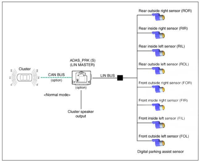
- PDW consists of 8 sensors (front: 4 units, rear : 4 units) that are used to detect obstacles and transmit the result in three separate warning levels, the first, second and third to IBU via LIN communication.
- IBU decides the alarm level by the transmitted communication message from the slave sensors, then operates the buzzer or transmits the data for display.
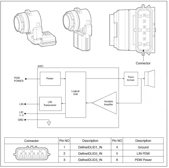
Block Diagram
System Operation Specification
Initial mode
- System initializing time
- PDW-F : 500ms after IGN1+ initial D Gear + below 10 Km h
- PDW-R : 500ms after IGN1+ initial R Gear
- PDW recognizes LID and sets the sensor ID up during initialization.
- PDW activates each sensor and then executes the diagnosis after finishing initialization of IPM(IBU).
- PDW starting buzzer is normally worked, when sensor does not send an error message and after finishing error diagnosis.
- If any failure is received from the any sensors, PDW starting buzzer
does not work but the failure alarm is operated for a
moment.
If you have display option, warning sign is also shown on it.
WARNING
Buzzer for sensor failure is operated once, but display is shown continuously until it is repaired completely.
- IBU memorizes the completed initializing status of sensor.
Normal mode
- PDW-F : Lin communication starts and keeps the routine after IGN1 ON-D
gear + below 10 km/h.
PDW-R : Lin communication starts and keeps the routine after IGN1 ON-R gear
- After initializing, the routine starts at once without PDW starting warning sound.
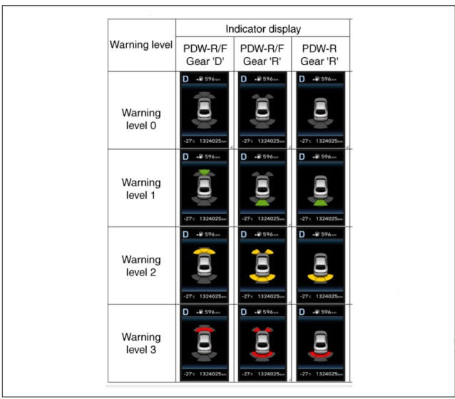
- Alarms of obstacle consists of 3 level 1,2,3 step and 1,2 alarm sounds intermittently and 3 alarm sounds continuously. 1 level alarm doesn't exist in the front ultrasonic sensor.
- In display, the data of each sensor is sent from IBU to display, for example cluster. CAN communication is used for transmission and maximum gateway time is 50ms.
- The efficient vehicle speed of PDW operation is under lOKm h.
- Operation doesn't start or stops at gear N. P.
Sensing Area
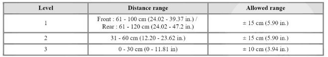
*Measurement condition : PVC pipe - Diameter 75 mm (0.0394 in.), length 1 m (39.37 in.), at normal temperature
Display Alarm Indicator Specification
Component Location
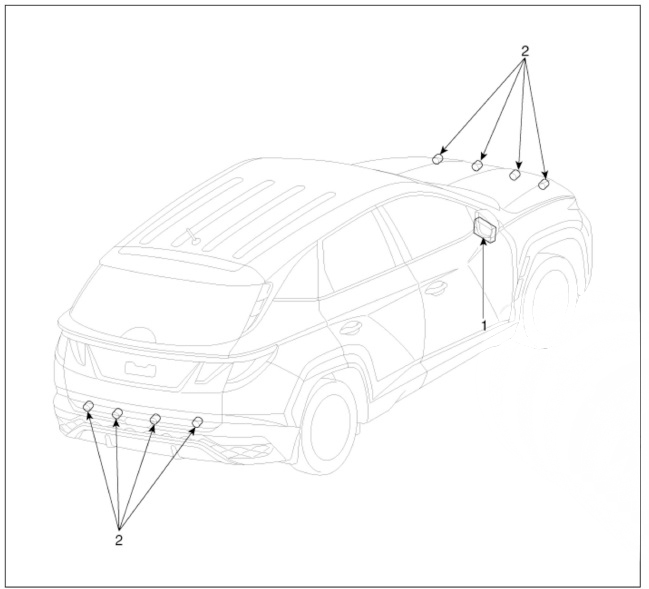
- ADASJPRK (S)
- Ultrasonic Sensor
PDW function is applied alone, it is integrated into ADASJPRX (S)
Specifications
ADAS PRK Application Specification (Valeo)
Schematic Diagrams
Removal
- Disconnect the negative (-) battery terminal.
- Remove the front/rear bumper assembly.
(Refer to Body - "Front Bumper Assembly") (Refer to Body - "Rear Bumper Cover")
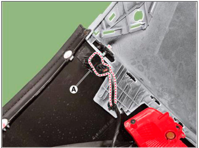
- Disconnect the connector from the parking distance warning sensor.
- Pull out the sensor (A) by opening the sensor holder out.
Installation
- Install the Parking distance warning sensor after connecting the connector.
- Install the front/rear bumper cover.
- Connect the negative (-) battery terminal.
READ NEXT:
 Surround View Monitor (SVM) - Description
Surround View Monitor (SVM) is the system that allows video monitoring of 360
degrees around the vehicle. The system
includes 4 ultra optical camera mounted around the vehicle (front, both sides,
rear).
The video from these cameras are applie
Troubleshooting
WARNING
1) After replacing controller, always check that the system operates
properly.
2) If the failure persists after replacing the controller, do not
replace the controller.
Inspection by DTC Code
Inspection for Defect in S
SEE MORE:
Vehicle parasitic current inspection
Inspection
Using the Ammeter
Turn the all electric devices OFF, and then turn the ignition switch OFF.
Close all doors except the engine hood, and then lock all doors.
(1) Disconnect the hood switch connector.
(2) Close the trunk lid.
Camshaft - Inspection
Measure the height of the cam.
Check the surface of the cam lob for wear and tear. If necessary, replace the
camshaft.
Cam height
Intake : 37.33 mm (1.4697 in.)
Exhaust : 37.44 mm (1.474 in.)
Inspect the camshaft journal clearance.
Information
- Home
- Hyundai Tucson - Fourth generation (NX4) - (2020-2023) - Owner's Manual
- Hyundai Tucson - Fourth generation (NX4) - (2020-2023) - Workshop Manual
