Hyundai Tucson: Surround View Monitor (SVM) - Description
Surround View Monitor (SVM) is the system that allows video monitoring of 360 degrees around the vehicle. The system includes 4 ultra optical camera mounted around the vehicle (front, both sides, rear).
The video from these cameras are applied with distortion compensation, time point conversion, and video merging technologies to provide sky-view image of the vehicle's surrounding area, as well as various other view modes.
The SVM System provides video feed of the vehicle's surrounding area while parking or during low speed driving to the driver to enhance safety and driver's convenience.
In addition, the system also displays video image of vehicle's surrounding area, and includes steering wheel synchronized guide line indication, front and rear object warning, and A/S (including In-Line) tolerance compensation features.
It's a system that displays the video, from ultra optical cameras mounted on 4 sides of the vehicle, on the Head Unit Screen. It shows 360 degrees sky-view image of the vehicle's surrounding area, as well as various other view modes. The SVM System provides video feed of the vehicle's surrounding area while the vehicle is parked or during low speed driving to the driver to enhance safety and driver's convenience.
Blind-spot View Monitor (BVM)
Blind-spot View Monitor (BVM) is a driving safety system that helps provide a more comprehensive views on areas which is not usually visible by the side mirrors when the vehicle tries to change the lane.
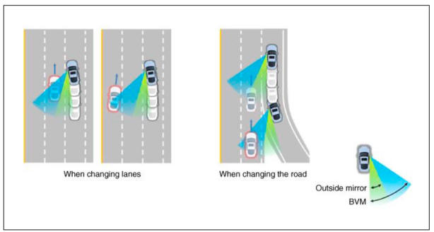
The BVM system provides a driver a more comprehensive view which is not usually visible by the side mirrors in certain situations like swithing drive lanes. The system helps to avoid any blind spot mishaps.
- The rear side view is displayed in the cluster screen when the turning lights are in operation as the turn signal light switch goes up and down by the driver.
- The SVM also provides an edited view of the left side/ right side without adding more cameras.
- I t helps minimize the distraction of the driver by displaying the rear side view that is usually hard to see.
WARNING
- The video will be played even though the side mirrors are folded. But it does not provide a proper view of the surroundings.
- The video quality may be lower than the SVM video as the size of the original image has to be adjusted to fit the cluster.
- The screen may temporarily fades out with changes in light conditions during daytime or with a sunrise or a sunset. Or when the car enters the tunnel.
- The view of the surrounding objects provided by the system may look far away than views that are obtained by the side mirrors.
- The brightness of the rear side video may change due to a mode switching delay of the SVM BVM.
Major Features
- Display Vehicles Surrounding in Video
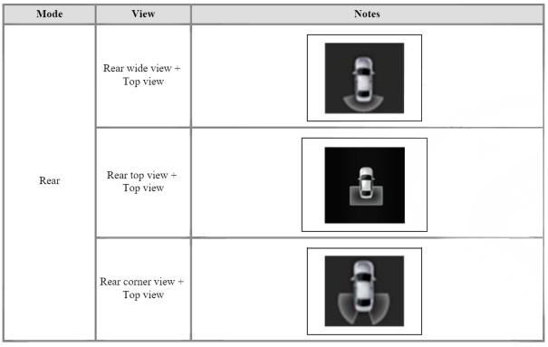
The surrounding area video display function displays the 360 degrees video image captured through 4 cameras to the driver through the Head controller Screen while the vehicle is moving at low speed or going reverse. The SVM System displays total of 8 video modes for displaying surrounding video based on the vehicle driving state and the driver's selection.
- Guide Line Indication & Steeling Wheel Synchronized Feature
The Guide Line Indication & Steering Wheel Synchronized Feature is the function that assists the driver in parking by synchronizing the steering wheel with the rear view video display marked with a guide line to help anticipate the direction of the vehicle going reverse.
- Front/Rear Object Warning (Obstacle Detection Feature)
The system receives obstacle warning signal from the PAS or SPAS sensors mounted on the front/rear of the vehicle and displays the obstacle location on the SVM Head Unit Screen.
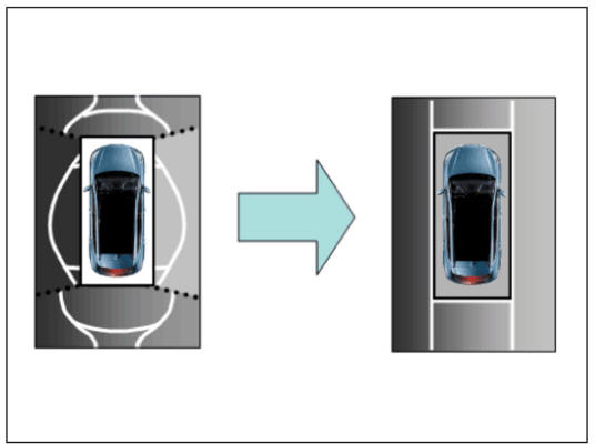
- Tolerance Compensation (including A/S)
Manual Tolerance Compensation Software is embedded in the SVMECM to compensate the SVM deviation that may occur due to assembly line installation tolerance. You must first setup proper work environment in order to perform correct tolerance compensation.
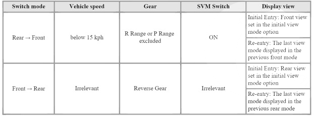
SVM Mode Entry Conditions
The vehicle information is accessed regularly, even after entering SVM mode. When the conditions are met, conversion from front mode to rear mode is available, and vice versa.
When the mode is converted, the view displayed on the screen can be the initial view or the previous view depending on the conditions.
If the mode for conversion is the initial entry, the default view is selected based on the front or rear. If a continuous front-rear conversion mode occurs as forward and backward movement are repeated for parking, the previous view is recalled and displayed.
- Initial Entry: When the rear and front mode view in SVM mode is displayed on the screen for the first time
- Re-entry: When switching from SVM mode to another mode, without turning off SVM, and returning to the previous mode (e.g. Rear -> Front -- Rear: Re-enter rear mode / Front -> Rear -> Front: Re-enter front mode
SVM Mode Disengagement
If the conditions below are satisfied while in SVM mode, the SVM is turned OFF and 110 video is displayed.
SVM Options
Considering the user's convenience, the SVM provides three options for the user to select.
The window for changing options (parking guide settings) is displayed by the AVN. Only the changed options are forwarded to the SVM controller through M CAN.
These three options are applied as soon as they have been selected by the user. Based on the conditions, the initial views displayed are as follows.

Operations for Guideline Steering Interlocking Indications
The indication for the guideline steering interlocking trace uses the steering wheel angle value periodically received by the SVM controller through C-CAN.
A rear area that displays a 130 degree image of the rear mode (two-split mode) and a wide view are displayed with the expected car movement trace.
- View modes for guideline steering interlocking indications
- Specifications for guideline steering interlocking trace lines
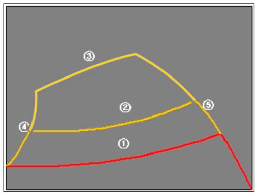
- Indications for neutral trace lines
If the steering angle is neutral, the neutral trace line is indicated in blue, which shows the expected movement trace of the car.
This line is displayed with the guideline steering interlocking trace line and is also a fixed line that is not interlocked with the steering angle operation.
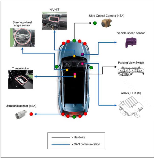
SVM system input/output
- Camera input
- SVM image display
The images received from the 4 cameras mounted on the vehicle go through the image distortion correction logic and the image merging process.H UNIT displays these images toghether with other additional features such as the parking guidelines linked with steering wheel on the AVN screen.
- Parking/view button
It is used as a control input signal to operate the front view mode function with the ignition switch ON.
- Ignition input
SVM controller displays the image only in the IGN1 ON and limits the image display with the SVM OFF in the IGN1 OFF.
SVM controller uses the signal which is input to the IGN pin or B-CAN message routed from the IGPM (gateway) to CCAN to judge the IGN1 ON/OFF.
- Chassis CAN input (C_CAN)
SVM controller receives the vehicle state information through the C_CAN to determine the operation of SVM major functions.
- Multimedia CAN input/output
Relevant information is processed by receiving the M-CAN signal routed from the IGPM (gateway) to C-CAN.
The routed M-CAN signal communication aims to transmit and receive the below information.
Components
READ NEXT:
 Troubleshooting
WARNING
1) After replacing controller, always check that the system operates
properly.
2) If the failure persists after replacing the controller, do not
replace the controller.
Inspection by DTC Code
Inspection for Defect in S
The Procedure of Manual Tolerance Compensation
Advanced preparations will be made according to the following.
Confirm that the car hood, trunk and door are closed.
The door is closed after getting in on the passenger side.
Unfold the side mirror if it is folded in.
Put the gear int
Ultra Optical Camera
Components
Ultra Optical Camera - RH LH
Ultra Optical Camera - Front
Ultra Optical Camera - Rear
Removal
WARNING
In case of bad quality or poor focus, be sure to check the camera
lense surface condition and
foreign materials.
SV
SEE MORE:
Differential Carrier Assembly- Installation
Installation
Install the differential carrier bracket (A).
Install the jack and intall the differential carrier assembly (A).
Tightening torque :
68.6 - 88.3 N m (7.0 - 9.0 kgf m , 50.6 - 65.1 lb ft)
Install the coupling ass
Vehicle Information, Consumer Information and Reporting Safety Defects
Exterior overview (I)
Front view
The actual shape may differ from the illustration
Hood
Headlamp
Tires and wheels
Side view mirror
Panoramic sunroof
Front windshield wiper blades
Windows
Front radar
Ex
Information
- Home
- Hyundai Tucson - Fourth generation (NX4) - (2020-2023) - Owner's Manual
- Hyundai Tucson - Fourth generation (NX4) - (2020-2023) - Workshop Manual
