Hyundai Tucson: Ultra Optical Camera
Components
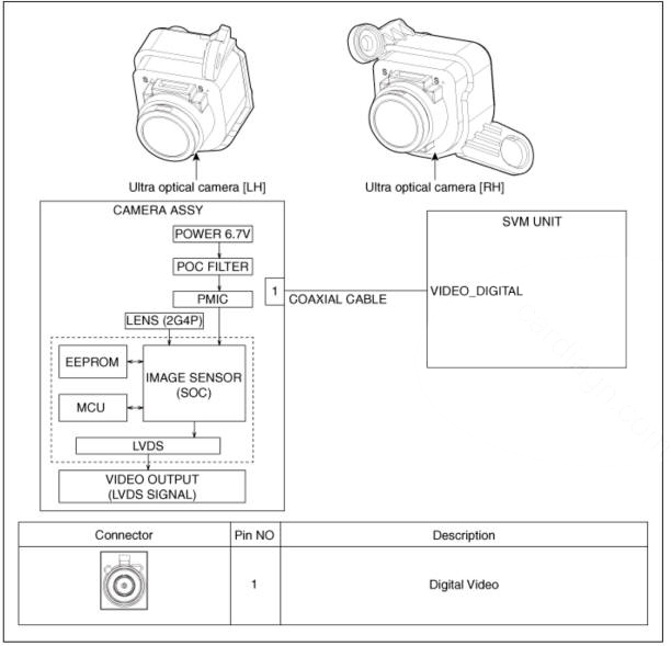
Ultra Optical Camera - RH LH
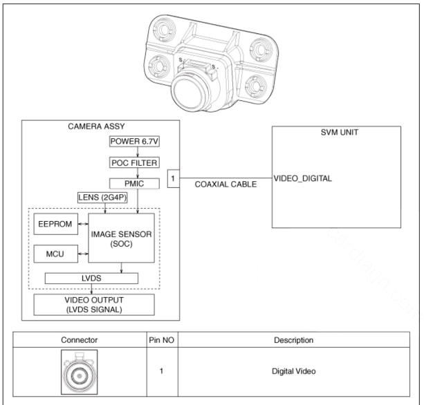
Ultra Optical Camera - Front
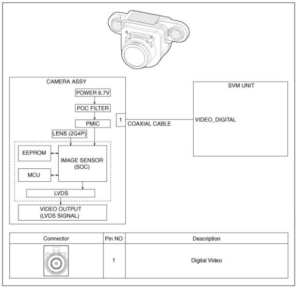
Ultra Optical Camera - Rear
Removal
WARNING
In case of bad quality or poor focus, be sure to check the camera lense surface condition and foreign materials.
SVM Front Camera
- Disconnect the negative (-) battery terminal.
- Remove the front bumper assembly.
(Refer to Body - "Front Bumper Assembly")
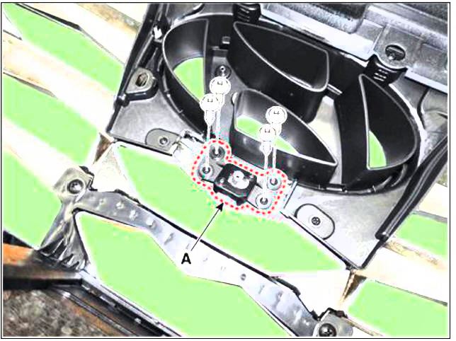
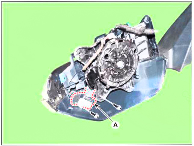
- Disconnect the SVM front camera connector (A).
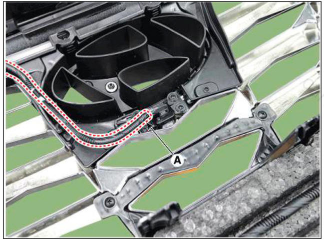
- Loosen the mounting screws and remove the SVM front camera (A)
SVM Rear Camera
- Disconnect the negative (-) battery terminal.
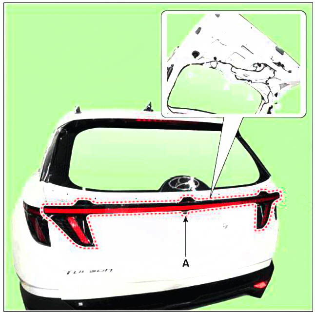
- Remove the tail gate back panel molding.
(Refer to Body - "Tail Gate Back Panel Molding")
- Disconnect the rear inside combination lamp connector (A).
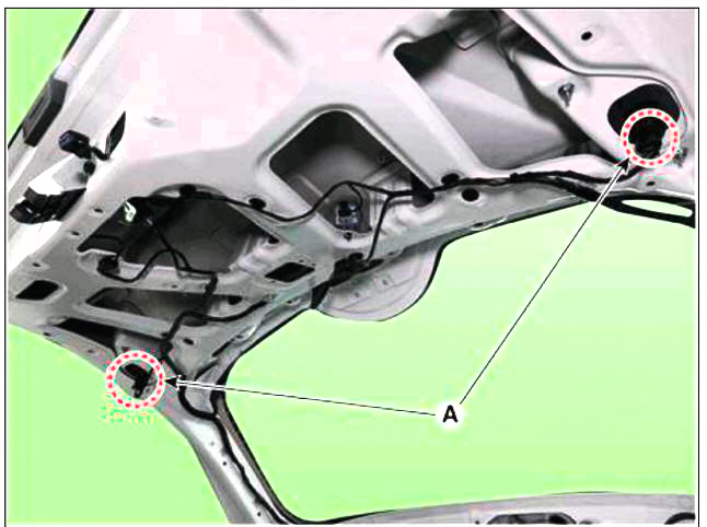
- Disconnect the rear view camera connector (A).
- Loosen the mounting nuts and remove the rear inside combination lamp (A).
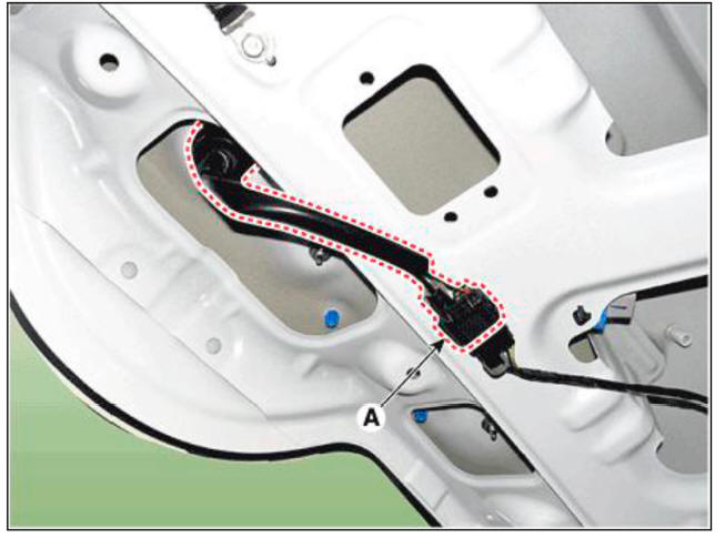
- Loosen the mounting screws and remove the rear view camera (A).
- Disconnect the rear view camera connector (A).

SVM Left/ Right Camera
- Disconnect the negative (-) battery terminal.
- Remove the outside mirror cover.
(Refer to Body Electrical System - "Power Door Mirror Actuator")
- Loosen the mounting screws and remove the SVM left/right camera (A).
Installation
SVM Front Camera
- Install the svm front camera.
- Install the front bumper assembly.
SVM Rear Camera
- Install the svm rear camera.
- Install the tail gate back panel molding.
SVM Left/ Right Camera
- Install the svm left/right camera.
- Install the door mirror.
Removal
WARNING
- When removing with a flat-tip screwdriver or remover, wrap protective tape around the tools to prevent damage to components.
- Put on gloves to prevent hand injuries.
WARNING
Take care not to bend or scratch the trim and panels.
- Disconnect the negative (-) battery terminal.
- Remove the console upper cover.
(Refer to Body - "Floor Console Assembly")
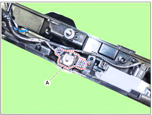
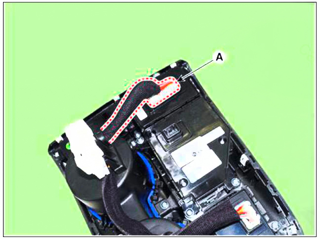
- Disconnect the SVM switch connector (A).
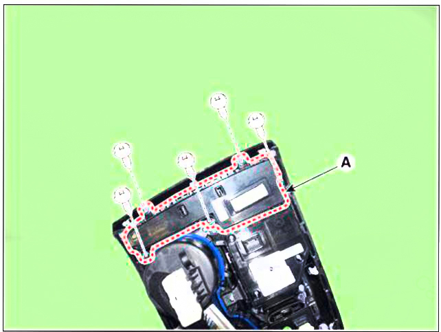
- Loosen the mounting screws and remove parking/view switch (A)
Installation
- Install the parking/view switch.
- Install the console upper cover.
- Connect the negative (-) battery terminal.
READ NEXT:
 Cruise Control System (CC) - Description
Description
The cruise control system is engaged by the cruise "ON/OFF" main switch
located on right of steering
wheel column. The system has the capability to cruise, coast, accelerate and
resume speed.
It also has a safety interr
Remote control switch
Components
Remote control switch (Audio swtich)
Remote control switch (Cruise control switch)
Circuit
Diagram
Trip+SCC+MSLA+LFA
Inspection
Check for resistance between terminals in right switch position.
Trip/Cruise
SEE MORE:
SRS care
The SRS is virtually maintenance-free
and there are no parts you can safely
service by yourself. If the SRS air bag
warning light does not illuminate when
the Engine Start/Stop button is in the
ON position, or continuously remains
on, we recomm
GPF Regeneration
This procedures is to forcibly regenerate the GPF with scan tool when the GPF
doesn't have been regenerated during driving. For
example, if the vehicle has repeated "Low speed driving" or "Short distance
driving", the GPF
Information
- Home
- Hyundai Tucson - Fourth generation (NX4) - (2020-2023) - Owner's Manual
- Hyundai Tucson - Fourth generation (NX4) - (2020-2023) - Workshop Manual
