Hyundai Tucson: ABS Does Not Operate/ ABS Does Not Operate (Intermittently)
ABS Does Not Operate
Detecting condition
Brake operation varies depending on driving conditions and road surface conditions, so diagnosis can be difficult. However if a normal DTC is displayed, check the following probable cause. When the problem is still occurring, replace the ESC control module.
- Faulty power source circuit
- Faulty wheel speed sensor circuit
- Faulty hydraulic circuit for leakage
- Faulty HECU
Inspection procedures
DTC Inspection
- Connect the diagnostic tool with the data link connector and turn the ignition switch ON.
- Verify that the DTC code is output.
- Is the DTC code output?

 Check the power source circuit.

 Erase
the DTC and recheck using diagnostic tool.
Erase
the DTC and recheck using diagnostic tool.
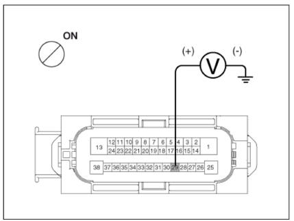
Check the power source circuit
- Disconnect the connector from the ESC control module.
- Turn the ignition switch ON, measure the voltage between terminal 29 of the ESC control module harness side connector and body ground.
Specification : approximately B -
Is the voltage within specification?

 Check the ground circuit.

 Check the harness or connector between the fuse (7.5A) in the engine compartment
junction block and the ESC control module. Repair if necessary.
Check the harness or connector between the fuse (7.5A) in the engine compartment
junction block and the ESC control module. Repair if necessary.

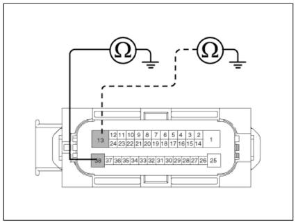
Check the ground circuit
- Disconnect the connector from the ESC control module.
- Check for continuity between terminals 13, 38 of the ESC control module
harness side connector and ground point.
Is there continuity?

 Check the wheel speed sensor
circuit.
Check the wheel speed sensor
circuit.

 Repair an open in the wire and
ground point.
Repair an open in the wire and
ground point.
Check the wheel speed sensor circuit
- Refer to the DTC troubleshooting procedures.
- Is it normal?

 Check the hydraulic circuit for leakage.

 Repair or replace the wheel speed
sensor.
Repair or replace the wheel speed
sensor.
Check the hydraulic circuit for leakage
- Inspect leakage of the hydraulic lines.
- Is it normal?

 The problem is still occurring, replace the ESC control module.

 Repair the hydraulic lines for leakage.
ABS Does Not Operate (Intermittently).
Detecting condition
Brake operation varies depending on driving conditions and road surface conditions, so diagnosis can be difficult. However if a normal DTC is displayed, check the following probable cause. When the problem is still occurring, replace the ESC control module.
- Faulty power source circuit
- Faulty wheel speed sensor circuit
- Faulty hydraulic circuit for leakage
- Faulty HECU
Inspection procedures
DTC Inspection
- Connect the diagnostic tool with the data link connector and turn the ignition switch ON.
- Verify that the DTC code is output.
- Is the DTC code output?

 Check the wheel speed sensor
circuit.
Check the wheel speed sensor
circuit.
 Erase the DTC and recheck using
diagnostic tool.
Erase the DTC and recheck using
diagnostic tool.
Check the wheel speed sensor circuit
- Refer to the DTC troubleshooting procedures.
- Is it normal?

 Check the stop lamp switch circuit.

 Repair or replace the wheel speed
sensor.
Repair or replace the wheel speed
sensor.
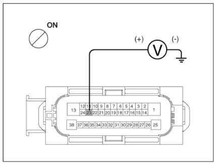
Check the stop lamp switch circuit
- Check that stop lamp lights up when brake pedal is depressed and turns off when brake pedal is released.
- Measure the voltage between terminal 23 of the ESC control module harness side connector and body ground when brake pedal is depressed.
Specification : approximately B +
Is the voltage within specification?

 Check
the hydraulic circuit for leakage.
Check
the hydraulic circuit for leakage.

 Repair the stop lamp switch. Repair
an open in the wire between the ESC control module and the
stop lamp switch.
Repair the stop lamp switch. Repair
an open in the wire between the ESC control module and the
stop lamp switch.
Check the hydraulic circuit for leakage
- Refer to the hydraulic lines.
- Inspection leakage of the hydraulic lines.
- Is it normal?

 The
problem is still occurring, replace the ESC control module.
The
problem is still occurring, replace the ESC control module.

 Repair the hydraulic lines for
leakage.
Repair the hydraulic lines for
leakage.
Communication with KDS is not possible.
(Communication with any system is not possible)
Detecting condition
Possible defect in the power supply system (including ground) for the diagnosis line.
- An open in the wire
- Poor ground
- Faulty power source circuit
Inspection procedures
Check The Power Supply Circuit For The Diagnosis
- Measure the voltage between terminal 16 of the data link connector and body ground.
Specification : approximately B +
Is voltage within specification?

 Check the ground circuit for the
diagnosis.
Check the ground circuit for the
diagnosis.

 Repair an open in the wire. Check
and replace fuse from the engine compartment junction block.
Repair an open in the wire. Check
and replace fuse from the engine compartment junction block.
Check the ground circuit for the diagnosis
- Check for continuity between terminal 4 of the data link connector and
body ground.
Is there continuity?

 Repair an open in the wire between terminal 4 of the data link connector and
ground point.
Repair an open in the wire between terminal 4 of the data link connector and
ground point.

Communication with KDS is not possible.
(Communication with ABS only is not possible)
Detecting condition
When communication with diagnostic tool is not possible, the cause may be probably an open in the HECU power circuit or an open in the diagnosis output circuit.
- An open in the wire
- Faulty HECU
- Faulty power source circuit
Inspection procedures
Check for Continuity in the CAN Line
- Disconnect the connector from the ESC control module.
- Check for continuity between terminals 26, 14 of the ESC control module connector and 3, 11 of the data link connector.
- Is there continuity?

 Check the power source of ESC
control module.
Check the power source of ESC
control module.

 Repair an open in the wire.
Check the power source of ESC control module
- Disconnect the connector from the ESC control module.
- Turn the ignition switch ON, measure the voltage between terminal 29 of the ESC control module harness side connector and body ground.
Specification : approximately B+
Is voltage within specification?

 Check for poor ground.

 Check the harness or connector
between the fuse (10A) in the engine compartment junction block and the ESC
control module.Repair it necessary.
Check the harness or connector
between the fuse (10A) in the engine compartment junction block and the ESC
control module.Repair it necessary.
Check for poor ground
- Check for continuity between terminal 4 of the data link connector and ground point.
- Is the electric current applied between groundings?

 Replace
the ESC control module and recheck.
Replace
the ESC control module and recheck.

 Repair
an open in the wire or poor ground
Repair
an open in the wire or poor ground
READ NEXT:
 When Ignition Key Is Turned ON (engine OFF), The ABS Warning Lamp Does Not
Light Up.
When Ignition Key Is Turned ON (engine OFF), The ABS Warning Lamp Does Not
Light Up.
Detecting condition
When current flows in the HECU the ABS warning lamp turns from ON
to OFF as the initial check. Therefore if the lamp does not light up. the
cause may be an open in the lamp power supply circuit, a blown bulb, an
open in the bo
Even After The Engine Is Started, The ABS Warning Lamp Remains ON
Detecting condition
If the HECU detects trouble, it lights the ABS warning lamp while at the
same time prohibiting ABS control. At this time, the HECU records a
DTC in memory. Even though the normal code is output, the ABS
warning lamp remains ON
ESC Control unit (HECU)
Components
Front - right (FR)
Rear - left (RL)
Rear - right (RR)
Front - left (FL)
MC2
MCI
ESC Control unit (HECU) connector
Bracket
ESC Control unit (HECU)- Removal
Removal
Disconnect the battery negative ( - ) terminal.
SEE MORE:
IMT System Actuator- Inspection
IMT system clutch tube and line
Remove the air cleaner assembly and the air duct.
(Refer to Engine Mechanical System - "Air Cleaner")
Check conditions (disassembled, damaged) of the clutch tube (A) and
check leakages of the co
IBU (Integrated Body Control Unit (IBU)
The IBU manages all function related to :
-"Start Stop Button (SSB) monitoring",
"Immobilizer communication" (with Engine Management System unit for
immobilizer release)
Authentication server" (Validity of Tran
Information
- Home
- Hyundai Tucson - Fourth generation (NX4) - (2020-2023) - Owner's Manual
- Hyundai Tucson - Fourth generation (NX4) - (2020-2023) - Workshop Manual
