Hyundai Tucson: The Procedure of Manual Tolerance Compensation
Hyundai Tucson - Fourth generation (NX4) - (2020-2023) - Workshop Manual / Advanced Driver Assistance System (ADAS) / Surround View Monitor (SVM) / The Procedure of Manual Tolerance Compensation
- Advanced preparations will be made according to the following.
- Confirm that the car hood, trunk and door are closed.
- The door is closed after getting in on the passenger side.
- Unfold the side mirror if it is folded in.
- Put the gear into neutral.
- In the preparation stage ahead of time an exhaust inhaler should not be installed as it can block the view of the rear camera.
- Also, the exhaust from the exhaust pipe can create a smokescreen blocking rear footage, therefore after using a fan to clear the exhaust the compensation work should be performed while in IGN (ignition).
- The foot brake or electro-mechanical parking brake should be engaged to prevent the car from moving.
- The following processes will be performed to confirm whether or not the SVM ECU and camera are working properly before engaging tolerance compensation mode.
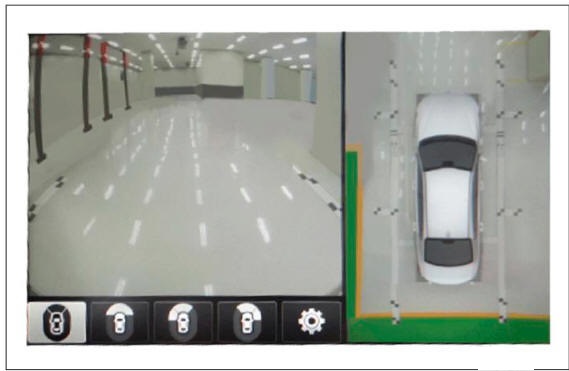
- Confirm that the initially set up video is showing up. (front view footage while the gear is in neutral + top view footage)
- Confirm that footage from the front, back, left and right is showing up properly.
- When the footage appears properly, the tolerance compensation mode will be engaged, and when footage is not showing up clearly or does not show up at all the part will have to be replaced.
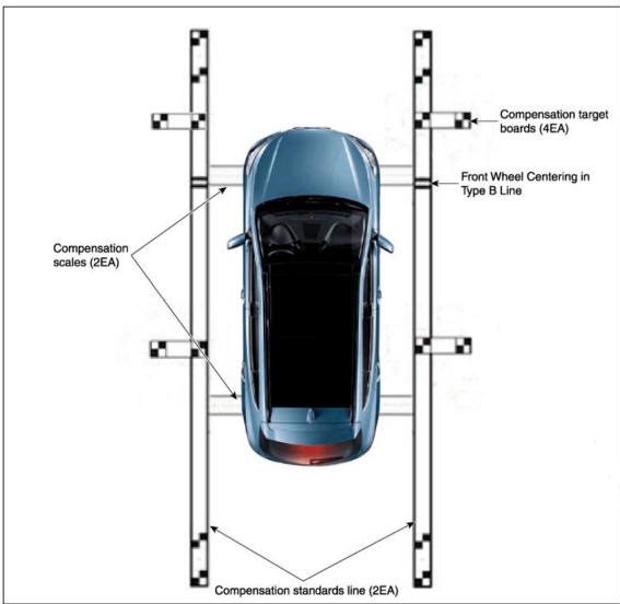
- Install around the vehicle by referring to the guide that was provided along with the compensation scales (2), compensation standard line boards (2). and compensation target boards (4).
WARNING
When centering the wheels on the compensation standards line board, the A-type and B-type must be centered separately.
Caution should be taken because the center location of the white and black compensation plate consist of standard coordinates the accuracy(distance / right-angles) are very important.
- The front and rear / left and right centering should be maintained within a deviation of 3cm.
- When centering the vehicle the rotation deviation should be maintained within 1 degree on the side.
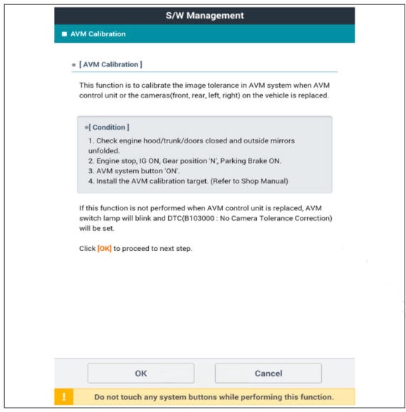
- Keep the IG on while the car is stopped, confirm the location of the gear stick is on 'N' and engage the parking brake on a flat area.
- Perform the work with the parking/view switch in the vehicle set to 'ON.'
- Perform SVM Calibration according to GDS diagnostics display.
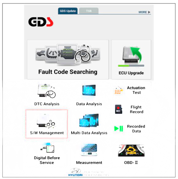
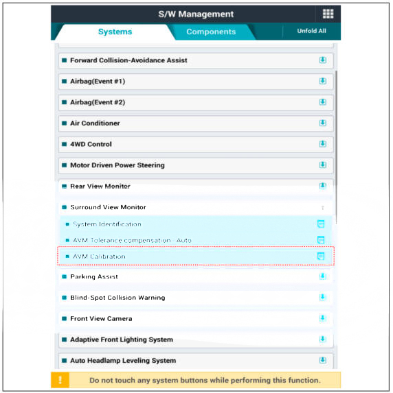
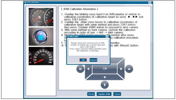
- Proceed with the AVM calibration according to the GDS screen.
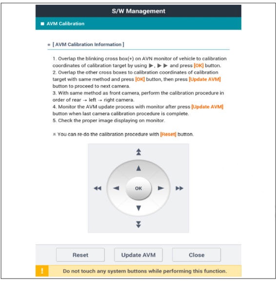
WARNING
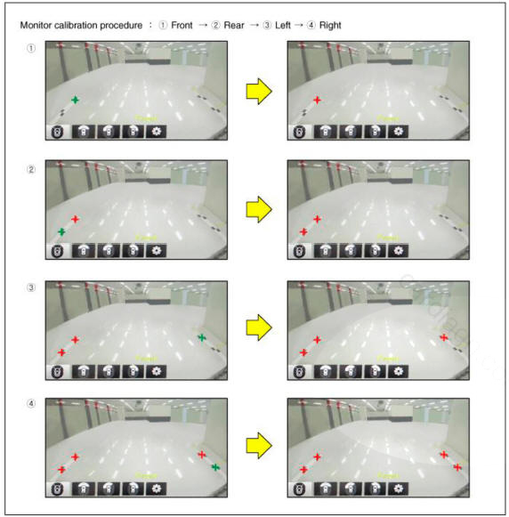
- Before matching the calibration point:"+" blinks in green color.
- When you click OK after matching the calibration point:"+" turns on in red color.
- After matching 4 forward correction points, click OK button and click Update AVM button to move to the next camera calibration.
- Perform the calibration in the order of front -> rear -> left
-> right camera.
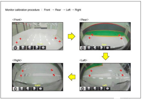
- After checking the vehicle and calibration line on the AVN monitor screen to see if the calibration has been performed properly, press the OK button.
When calibration has not been performed properly, press the Cancel button to match the calibration points again.
AVN Monitor
GDS Screen
Removal
- Disconnect the negative (-) battery terminal.
- Remove the crash pad center panel.
(Refer to Body - "Crash Pad Center Panel")
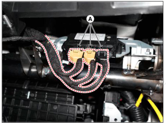
- Disconnect the SVM unit connector (A).
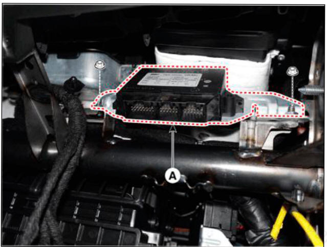
- Loosen the mounting nuts and remove the SVM Unit (A).
Installation
- Install the SVM unit.
- Install the crash pad center panel.
- Connect the negative (-) battery terminal.
READ NEXT:
 Ultra Optical Camera
Components
Ultra Optical Camera - RH LH
Ultra Optical Camera - Front
Ultra Optical Camera - Rear
Removal
WARNING
In case of bad quality or poor focus, be sure to check the camera
lense surface condition and
foreign materials.
SV
Cruise Control System (CC) - Description
Description
The cruise control system is engaged by the cruise "ON/OFF" main switch
located on right of steering
wheel column. The system has the capability to cruise, coast, accelerate and
resume speed.
It also has a safety interr
SEE MORE:
Manual heating and air conditioning
Start the engine.
Set the mode to the desired position.
For improving the effectiveness of
heating and cooling, select:
Heating:
Cooling:
Set the temperature control to the
desired position.
Set the air intake contr
Compressor
Components
Compressor
Components
Clutch bolt
Disc & Hub assembly
Snap ring (Rotor)
Pulley
Snap Ring (Stator)
Clutch spacer
Compressor
Electric Control Valve (ECV)
Electric Control Valve (ECV) snap ring
Removal
Information
- Home
- Hyundai Tucson - Fourth generation (NX4) - (2020-2023) - Owner's Manual
- Hyundai Tucson - Fourth generation (NX4) - (2020-2023) - Workshop Manual
